
Brochure/Catalogue
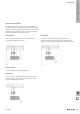


Surge protection with 3+1 circuitry in consumer loads
with TT power systems
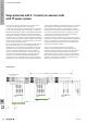
3+1 does not always equal 4! At least not in the case of
protective circuits with arresters in a TT system.
In a TT system the supply is via the three phase conductors
L1, L2 and L3 and the neutral conductor N, i.e. without an
additional integral PE conductor. The equipotential bonding
is then made separately within the consumer installation
through the earthing. The outcome of this is that the neutral
conductor can accommodate a higher voltage compared to
the earth potential. Therefore, to protect against overvoltages
between neutral conductor and earth potential, an arrester
must be incorporated here as well.
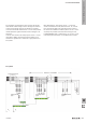
The “four-arrester circuit” does not satisfy all safety aspects.
Up to now, four arresters, i.e. one each between earth
potential and L1, L2, L3 and N, were installed in consumer
installations with TT systems. However, this “four-arrester
circuit” is no longer regarded as the optimum solution
because the physical characteristics of the varistors used
may lead to unacceptably high touch voltages at the PE
conductor in the consumer installation. Depending on
the age of the system, leakage currents can ow through
varistors and cause overvoltages via the earthing resistance.
The downstream RCD-(Fi) circuit breaker found in TT systems
cannot detect such leakage currents. Therefore it cannot
trigger. Furthermore, a failed, i.e. low-resistance, varistor
would create a connection between N and PE. One remedy
is to install an arrester disconnector in sequence with the
varistors. But an arrester disconnector that monitors the
varistors takes up space and costs extra.
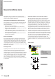
If instead of varistors, sparkover gaps were to be arranged
between the conductors and the equipotential bonding, then
that, too, would not be an ideal solution. The longer time
to sparkover and the characteristics of the sparkover gaps
result in higher residual voltages.
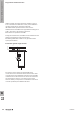
The 3+1 circuit includes varistors with the three L
conductors and the N conductor, and a sparkover gap
between the base of the three varistors at the N conductor
and the equipotential bonding rail (PE). The size of the
sparkover gap must be such that it can accommodate the
total current of the three phase conductors and the neutral
conductor. The sparkover voltage of the sparkover gap in
230 V systems should be 1.5...2 kV.
3+1 circuit: universal solution
3URWHFWLRQDFFWR,(&
5
%
5
$
)
)
)
)
/
/
/
1
3(
/
1
3(
:K
+3$6
3$6
/LJKWQLQJDUUHVWHU
7\SH,
2YHUYROWDJHDUUHVWHU
7\SH,,
(TXLSPHQWSURWHFWLRQ
7\SH,,,
6HUYLFH&RQQHFWLRQER[
TN-S system
W
The basics of lightning and surge protection
W.16 2028840000