
Brochure/Catalogue


Surge protection installation instructions
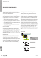
5.1 Replacements
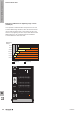
When an arrester has a red window (as described by point
5) or a red LED, then the arrester should be replaced by a
qualied electrician. The individual Type I-I/II arresters are
pluggable and coded for voltage.
For the insulation resistance test, the SPD must be
disconnected from the facility during the duration of the
measurement (e.g. by pulling out the upper sections) or
the arresters are disconnected from the power network.
Weidmüller provides special notice stickers for the electrical
cabinet (order number 1287670000) for this purpose. A
proper arrester that matches the nominal voltage must be
re-installed.
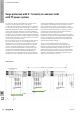
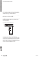
6 Connecting the remote signalling (R)
The signal contact is designed as a change-over (CO)
contact. It is connected to terminals 11 and 14. Terminals
11/12 are in normal operation (window is green) closed and
terminals 11/14 are open. In the event of an error (red box),
the connecting terminals 11/14 are closed and 11/12 are
open.
For the VPU III, the response of the isolating mechanism is
signalled when a non-reversible thermal fuse opens.
The alert circuit is connected using cables with a maximum
cross-section of 1.5 mm². The connecting cables must not
be run parallel to the earthing cable. A protective circuit
using ne surge protection (Type III) according to the voltage
level can reduce interference on and in the evaluation device.
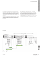
7 Back-up fuse
The lightning and surge protection devices in the VPU I and
VPU II series behave passively during normal operation. No
current is drawn. This provides the necessary protection
against short circuits and overloads by using a fuse that is
designed for the installation method and the cross-section of
the connected cable. The VPU product series is also tested
with a maximum back-up fuse. This back-up fuse is listed in
the technical specications or the side label on the product.
If the fuse used in the system has a smaller or equal value,
then it can be used for cable protection on the power feed.
If the power-feed fuse has a value greater than the fuse
specied in the technical specications, additional fuses
must be integrated depending on the connecting cable in
the wiring harness of the VPU module. Remember that the
fuse for the wiring harness is also capable of carrying a
lightning current. This fuse should not be too small which
would make the SPD ineffective during an actual power
surge.
8 Application
The VPU I LCF and VPU I establish the required lightning
protection equipotential bonding for existing lightning
protection systems and power feeds. The encapsulated VPU
I LCF and VPU I are preferably used in the distributors in
building installations.
The VPU I LCF products can be used before the meter, since
this does not cause leakage current during operation. The
VPU I LCF and the VPU I have been certied as lightning
protection as well as surge protection. This means that
they are permitted for Type I and Type II (whereby the VPU
II surge protector is permitted for Type II and III) – surge
protection and end-device surge protection. VPU III and VPO
DS are Type III surge protectors for end devices.
9 Approvals
The VPU I-, VPU II- and VPU-III series have a CB report and
can thus be rewritten for country-specic approvals.
All products bear the CE mark.
10 A brief overview of the installation standard for
lightning and surge protection
Based on VDE 0100-534, derived from the IEC 60364-5-53
standard. This standard species the surge protection
(Type I or II) that should be installed.
The IEC 60364-5-534 standard may not be the same as the
adopted standards from each country. The country-specic
standards and application-based standards or rules must be
observed during the installation. The installation must be
carried out by locally licensed professionals.
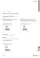
The VDE 0100-534 distinguishes between the connection
diagrams A, B and C.
The following is derived in actual practice:
A = 3+0 circuitry (VPU I 3 or VPU II 3 in the TN-C system)
B = 4+0 circuitry (VPU I 4 or VPU II 4 in the TN-S system)
C = 3+1 circuitry (VPU I 3 +1 or VPU II 3+1 in the PU II
TN-S/TT or IT system with N).
W
The basics of lightning and surge protection
W.232028840000