
Brochure/Catalogue


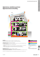


Components for Surge protection
4. Combination circuits
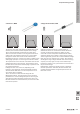
Combining the components described above results
in surge protection products that can match individual
requirements. If a voltage pulse reaches the input of such a
combination circuit, then the gas discharge tube is red and
discharges high current. The residual pulse is attenuated by
a downstream inductance and subsequently received and
limited by the varistor and/or suppression diode. If the gas
discharge tube is not triggered, i.e. in the case of a slower
voltage rise, then the pulse is discharged by the varistor or
the suppression diode alone.
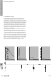
The sequence of the individual components results in an
increasing response sensitivity towards the output. An
interference voltage with a rise of 1 kV/µs and a peak value
of 10 kV at the input is limited by a gas-lled surge arrester
to approx. 600-700 V. The second stage, decoupled from
the rst by means of an inductance, suppresses this value to
approx. 100 V. This voltage pulse is then reduced to approx.
35 V (in a 24 V protective combination) by the suppression
diode. Therefore, the downstream electronics need only be
able to cope with a voltage pulse of approx. 1.5 x U
B
.
V
600
500
400
300
200
100
0
0
1
2 µs
V
600
500
400
300
200
100
0
0
1
2 µs
V
600
500
400
300
200
100
0
0
1
2 µs
10
kV
8
6
4
2
0
0
10 20 30
µS
Surge voltage wave
U
U
B
W
The basics of lightning and surge protection
W.30 2028840000