Power Monitor Handbuch
1.1 Revisionsverlauf Version Datum Änderung 0.0 02/2013 Erstausgabe 1.0 05/2012 Kapitel 3.1 „Sicherheitshinweise“: Ergänzung zur Schutzisolierung Kapitel 4.1 „Messdaten“: Ergänzung zur Eingangsmessspannung Kapitel 6.4 „RS485Kommunikation“: Ergänzung zur RS485Verkabelung Kapitel 10.1 „Gerät“: Ergänzung zur Isolation Kapitel 10.3 „Spezifikationen zur Kommunikation“: Ergänzung zum Trennstatus 1.2 Kontaktadresse Weidmüller Interface GmbH & Co.
Inhaltsverzeichnis Inhaltsverzeichnis 1.1 Revisionsverlauf................................................................................................................................ 3 1.2 Kontaktadresse ................................................................................................................................. 3 Inhaltsverzeichnis .............................................................................................................. 4 2. Einleitung ...................
Inhaltsverzeichnis 7.3 Passwort zurücksetzen .................................................................................................................. 30 7.4 Einstellungen ................................................................................................................................... 31 7.4.1 Einstellungen für die Leistungsmessung ................................................................................ 31 7.4.2 Einstellungen für die Kommunikation ..................
Inhaltsverzeichnis 9.6 Installation eines USB-Treibers ................................................................................................... 111 10. Technische Daten ............................................................................................. 112 10.1 Gerät ............................................................................................................................................... 112 10.2 Eingangsspezifikationen ......................................
Einleitung 2. Einleitung 2.1 Marken- und Urheberrecht • Weidmüller besitzt das Urheberrecht für das vorliegende Handbuch. HINWEIS • Das Handbuch darf ohne vorherige Genehmigung weder ganz noch teilweise in irgendeiner Form oder mit irgendwelchen Mitteln vervielfältigt werden. HINWEIS (blau) weist auf eine gefährliche Situation hin, die, wenn sie nicht vermieden wird, zu Sachschäden führen kann. • Beim Modbus-Protokoll handelt es sich um ein Kommunikationsprotokoll, das von Modicon Inc.
Sicherheitsanweisungen 3. Sicherheitsanweisungen 3.1 Sicherheitshinweise VORSICHT! HINWEIS Ein Bedienungsfehler kann zu schweren Verletzungen des Bedieners oder zu Schäden an der Ausrüstung führen. • Lesen Sie das Handbuch sorgfältig vor der Installation und Wartung durch, damit ein ordnungsgemäßer Betrieb gewährleistet ist. • Machen Sie sich vor der Verwendung mit der Ausrüstung sowie mit den Sicherheitshinweisen und Anweisungen vertraut.
Sicherheitsanweisungen 3.2 Allgemeine Beschreibung Informationen zum Produkt Der Power Monitor ist in erster Linie für das Management von Energieeinsparungen konzipiert. Er ist nicht für Abrechnungszwecke bestimmt und kann außerdem aus rechtlichen Gründen nicht hierfür verwendet werden.
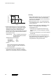
Stoßspannung (%) Sicherheitsanweisungen Messung 100 90 • Wenn Oberschwingungen oder Verzerrungen der Wellenform auftreten, können die Messungen ungenau sein. Überprüfen Sie das Stromsystem, bevor Sie es verwenden. Spitze 50 30 0 0 1,2 50 Zeit (μs) • Externes Rauschen bis zur unten angezeigten Höhe wird als Störspannung behandelt. Höhere Werte können jedoch zu Fehlfunktionen oder Schäden an der internen Schaltung führen.
Sicherheitsanweisungen 3.3 Elektrische Vorsichtsmaßnahmen • Wir empfehlen Ihnen daher das Passwort zu notieren, nachdem Sie es angelegt oder geändert haben. Statische Elektrizität • Entladen Sie statische Elektrizität durch Berühren von geerdetem Metall usw., wenn Sie das Gerät berühren. • Vor allem an trockenen Orten kann sich eine übermäßige statische Elektrizität aufbauen.
Beschreibung des Gerätes 4. Beschreibung des Gerätes Der Power Monitor wird verwendet, um elektrische Leistung, Leistungsfaktor, Frequenz usw. mit Wechselspannungseingang und Wechselstromeingang mit einem der folgenden Systeme zu messen: EinphasenZweileiter, Einphasen-Dreileiter, Dreiphasen-Dreileiter oder Dreiphasen-Vierleiter. Zur Kontrolle verfügt das Gerät über einen eingebauten Thermistor, um die Temperatur am Aufstellungsort (z. B. innerhalb der Schalttafel) zu messen.
Beschreibung des Gerätes 4.
Übersicht und Bedienung des Gerätes 5. Übersicht und Bedienung des Gerätes 5.
Übersicht und Bedienung des Gerätes 5.
Verdrahtung 6. Verdrahtung Achten Sie auf eine korrekte Verdrahtung, die der Klemmenanordnung und den Schaltbildern entspricht. Verbinden Sie aus Sicherheitsgründen und zum Schutz des Geräts eine Sicherung oder einen Sicherungsautomaten mit dem Netzteil. Es verfügt weder über einen integrierten Netzschalter, Sicherungsautomaten noch über eine Sicherung für gemessene Eingangsspannungsteile. Diese sollten daher in der Schaltung in der Nähe des Gerätes installiert werden.
Verdrahtung HINWEIS Die Eingangsspannung der einzelnen Klemmen beträgt: Klemme Stromversorgung Gemessener Spannungseingang 6.2 Phasen- und Leitersystem Klemmen-Nr.
Verdrahtung 6.2.1 Messen einer Last mit Nenneingangsspannung Einphasen-Zweileiter-System • Es wird ein Stromwandler (CT) benötigt, um ein Einphasen-Zweileiter-System (1P2W) zu messen. • 2 CTs sind notwendig, um 2 Lasten zu messen und 3 CTs, um 3 Lasten zu messen. • Zum Messen von 2 Lasten müssen die Leiter 3 und 4 verdrahtet werden. Zum Messen von 3 Lasten müssen die Leiter 3, 4 und 5 verdrahtet werden. 18 1444120000/01/05.
Verdrahtung Einphasen-Dreileiter-System/Dreiphasen-Dreileiter-System • 2 CTs werden benötigt, um ein Einphasen-Dreileiter-System (1P3W) und ein Dreiphasen-Dreileiter-System (3P3W) zu messen. Dreiphasen-Vierleiter-System • Es werden 3 CTs benötigt, um ein Dreiphasen-Vierleiter-System (3P4W) zu messen. 1444120000/01/05.
Verdrahtung 6.2.2 Messen einer Last mit hoher Eingangsspannung • Es wird ein Spannungswandler (VT) benötigt, um bei hoher Eingangsspannung eine Last zu messen. • Verwenden Sie einen VT, dessen sekundäre Nennspannung 110 V beträgt. • Eine Erdung der Sekundärseite des VT und CT ist bei einer Niederspannungsschaltung nicht erforderlich. 6.3 Montage des Stromwandlers (CT) GEFAHR! • Öffnen Sie niemals den Sekundärkreis des Stromwandlers (CT), wenn Strom an der Last anliegt.
Verdrahtung • Wenn Oberschwingungen oder Verzerrungen der Wellenform auftreten, können die Messungen ungenau sein. Überprüfen Sie das Stromsystem, bevor Sie es verwenden. • Die Messspannungseingangsklemme und der Stromwandler (CT) sollten getrennt voneinander verdrahtet werden. Durch Störeinstrahlungen können ansonsten die Anforderungen an die Messgenauigkeit nicht erfüllt werden. Anschluss des Stromwandlers (CT) (1) Schalten Sie die gemessenen Geräte aus.
Verdrahtung Einstellen der Parameter des Stromwandlers (CT) (1) Wählen Sie den geeigneten Stromwandlertyp (C-T) aus. (Wählen Sie „5 A“, wenn der sekundärseitige Strom des verwendeten Stromwandlers 5 A beträgt. Wählen Sie „1 A“, wenn der sekundärseitige Strom des verwendeten Stromwandlers 1 A beträgt.) (2) Stellen Sie den primärseitigen Strom des gemessenen Stromwandlers im Einstellmodus auf primärseitigen Strom (CT-1).
Verdrahtung 6.4 RS485-Kommunikation • Wird ein geschirmtes Kabel für die RS485-Übertragungsleitung verwendet, muss ein Ende geerdet sein. • Verwenden Sie zum Erden eine geeignete Erdung der Klasse D. Die Erdungsleitung darf nicht zugleich für andere Geräte genutzt werden (Abb. 1). • Bei beidseitigen Klemmenstationen, inkl. des oberen Geräts, sollten Abschlusswiderstände angeschlossen werden. Der Power Monitor hat keine eingebauten Abschlusswiderstände.
Verdrahtung Power Monitor und die anderen Geräte mittels 2-Leiter-System verbinden 6.5 Niederspannungsrichtlinie Bei Verwendung in einer Anwendung, die den Anforderungen von EN 61010-1 / IEC 61010-1 entspricht, muss sichergestellt sein, dass die folgenden Bedingungen erfüllt sind. Bei einer Verwendung gemäß Messkategorie III sind zwischen den Stromversorgungsleitungen und dem Messspannungseingang Varistoren zu installieren.
Einstellungen 7. Einstellungen Sie können die Parameter für Messungen und andere Funktionen mithilfe der Tasten am Power Monitor einstellen. Nach der Verdrahtung von Power Monitor und Stromwandler (CT) kann das Gerät eingeschaltet werden. Stellen Sie anschließend die Parameter für die Leistungsmessung ein, damit der Power Monitor die elektrische Leistung messen kann. Um die anderen Funktionen verwenden zu können, müssen die anderen Parameter entsprechend eingestellt werden.
Einstellungen Parameter für optionale Funktionen Messgröße Bereich Ausgangswert Auto-AUS 0 bis 99 [min.] 1 Helligkeit 1, 2, 3, 4, 5 (1: dunkel bis 5: hell) 3 Auto-Anzeige Start 0 bis 99 [min.] 10 Anzeige-Zyklus 1 bis 99 [s] 5 Temperaturkorrektur –100,0 bis 100,0 0.
Einstellungen 7.1 Arbeitsablauf beim Einstellen Ein Pfeil zeigt die Tasten an, die gedrückt werden müssen. - Drücken Sie , wenn Sie den Einstellwert einer Option ändern möchten. 1444120000/01/05.
Einstellungen Drücken Sie , um das Bestätigungsfenster aufzurufen. Wählen Sie [YES] und drücken Sie , um den Einstellwert zu definieren. Wird kein Wert geändert, wird das Bestätigungsfenster übersprungen und stattdessen die Messwertanzeige angezeigt. Hinweise 1) Wird übersprungen, wenn [0] für die Auto-Anzeige eingestellt ist. 2) Wird übersprungen, wenn [YES] zum Zurücksetzen aller ganzzahligen Werte ausgewählt wird. 7.
Einstellungen Wenn das Passwort falsch ist, wird [FAIL] angezeigt und Sie kehren zum Passwort-Eingabefenster zurück. HINWEIS Wenn Sie 5 mal ein falsches Passwort eingeben, wird die Passworteingabe eine Stunde lang gesperrt. 1444120000/01/05.
Einstellungen 7.3 Passwort zurücksetzen Wenn Sie das Passwort vergessen haben, können Sie es mit dem folgenden Verfahren zurücksetzen. (Ausgangswert: [0000]) Es ist nicht möglich, das eingestellte Passwort zu entschlüsseln. Messwertanzeige Drücken Sie , um zum Passwort-Eingabefenster zu wechseln. Drücken Sie 30 Sekunden lang im Passwort-Eingabefenster und - , um zum Fenster zum Zurücksetzen des Passworts zu gelangen.
Einstellungen 7.4 Einstellungen Einstellungen vor der Messung Wählen Sie mit - die gewünschte Einstelloption und drücken Sie anschließend , der betreffende Wert beginnt zu blinken. Verwenden Sie
- und zum Einstellen. Wählen Sie [YES] im Bestätigungsfenster aus und drücken Sie , um die Einstellwerte zu bestätigen. 7.4.1 Einstellungen für die Leistungsmessung Phasen-/Leitersystem SYST Wählen Sie das Phasen-/Leiter-System aus, das gemessen werden soll.
Einstellungen Primärseitiger Strom des CT CT-1 Stellen Sie den primärseitigen Strom ein, der vom Stromwandler (CT) verwendet werden soll. Geben Sie den primärseitigen Strom des Stromwandlers (CT) ein, der in der Einstellung des CTTypen definiert ist. Drücken Sie zum Einstellen - , . [Einstellbereich] 1 bis 4.
Einstellungen Umrechnungsrate (P) RATE P Stellen Sie die Umrechnungsrate für die integrierte Wirkleistung auf 1 kWh. Drücken Sie zum Einstellen - , . [Einstellbereich] 0,00 bis 99,99 / 1 kWh (Vorgabeeinstellung: 10,00) Erhöhen Verringern Umrechnungsrate (-P) RATE -P Stellen Sie die Umrechnungsrate für die integrierte Exportleistung (-P) auf 1 kWh. Drücken Sie zum Einstellen
- , .
Einstellungen 7.4.2 Einstellungen für die Kommunikation Protokoll PROT Wählen Sie das Protokoll für das Gerät aus, das für die Kommunikation über die serielle Schnittstelle (RS485) verwendet werden soll. Hinweis 1) Wird das Protokoll geändert, werden Gerätenummer, Übertragungsgeschwindigkeit (Baudrate), Übertragungsformat, Stopp-Bit und Ansprechzeit auf die Vorgabeeinstellungen zurückgesetzt. Drücken sie - , , um das Protokoll auszuwählen.
Einstellungen Übertragungsgeschwindigkeit (Baudrate) SPD Wählen Sie die Übertragungsgeschwindigkeit aus, die für die serielle Kommunikation (RS485) verwendet werden soll. Wählen Sie eine Übertragungsgeschwindigkeit aus, die dem verwendeten Master (SPS usw.) entspricht. Drücken Sie zum Auswählen - , . [Auswahlliste] 1.200, 2.400, 4.800, 9.600, 19.200, 38.400 [bps] (Vorgabewert: 19.200) Übertragungsformat FMT * Wählen Sie [8b-E] aus, wenn [645] für das Protokoll eingestellt ist.
Einstellungen Stopp-Bit STOP * Wählen Sie [1] aus, wenn [645] für das Protokoll eingestellt ist. Wählen Sie das Stopp-Bit aus, die für die serielle Kommunikation (RS485) verwendet werden soll. Drücken Sie zum Auswählen - , . [Auswahlliste] 1, 2 (Voreinstellung: 1) Ansprechzeit RESP * Wählen Sie einen Wert von 50 oder höher aus, wenn [645] für das Protokoll eingestellt ist. Stellen Sie die Ansprechzeit ein, die bei der seriellen Kommunikation (RS485) des Gerätes verwendet werden soll.
Einstellungen 7.4.3 Einstellungen für optionale Funktionen Auto-AUS OFF Die LCD-Anzeige schaltet sich automatisch aus, wenn für längere Zeit keine Taste betätigt wird. Nachdem die eingestellte Zeit abgelaufen ist, wird die Hintergrundbeleuchtung ausgeschaltet. Drücken Sie zum Einstellen - , . [Einstellbereich] 0 bis 99 min.
Einstellungen Auto-Anzeige AUTO DISP Hierdurch werden die Optionen aller ganzzahligen Werte automatisch geändert. Wenn die Einstellzeit nach Betätigung einer Taste verstreicht, wird der ganzzahlige Wert automatisch geändert. Drücken Sie zum Einstellen - , . [Einstellbereich] 0 bis 99 min.
Einstellungen Temperaturkorrektur TEMP CORRE Die gemessene Temperatur kann zur Anzeige korrigiert werden. Drücken Sie zum Einstellen - , . [Einstellbereich] –100,0 bis 100,0 (Voreinstellung: 0,0) Erhöhen Verringern Alle ganzzahligen Werte zurücksetzen RESET ALL Die integrale Leistung (Wirk-, Blind-, Scheinleistung) kann einmal zurückgesetzt werden. Drücken Sie zum Auswählen
- , .
Einstellungen Ganzzahligen Wert 2 zurücksetzen RESET 2 * Diese Option wird übersprungen, wenn [YES] zum Zurücksetzen aller ganzzahligen Werte ausgewählt wird. Zurücksetzen der Integralleistung von 2CH/2-Phase (Wirk-, Blind-, Scheinleistung) und integraler Exportleistung 2CH/2-Phase (Wirk-, Blindleistung). Drücken Sie zum Auswählen - , .
Einstellungen Version VER Gestattet die Überprüfung der Softwareversion. Anzeige der Softwareversion. 1444120000/01/05.
Einstellungen 7.4.4 Passwort-Einstellung Passwort-Einstellung PASS Sie können ein Passwort zum Ändern der Einstellungen festlegen. Das Passwort muss vor dem Wechsel zum Einstellmodus eingegeben werden. Wir empfehlen, ein Passwort einzustellen, um versehentliche Änderungen zu vermeiden. Drücken Sie , anschließend blinkt [0] auf der linken Seite. Stellen Sie mit - , das Passwort ein. Erhöhen Verschiebt die rechts eingegebene Ziffer. Die Einstellung erfolgt von links nach rechts.
Einstellungen 7.4.5 Bestätigungsfenster Einstellmodus Wenn Sie in einem beliebigen Bestätigungsfenster drücken, gelangen Sie zum Bestätigungsfenster. [Auswahlliste] YES, NO (Voreinstellung: NO [Nein]) Abbrechen Bestätigen Bestätigung der Änderung: Änderung abbrechen: [NO] [YES] Messwertanzeige 1444120000/01/05.
Anzeige der einzelnen Werte 8. Anzeige der einzelnen Werte 8.1 Bedienung der Monitoranzeige Ein Pfeil zeigt die Tasten an, die gedrückt werden müssen: - 44 1444120000/01/05.
Anzeige der einzelnen Werte *1 Wenn die 2. und 3. Last nicht gemessen werden, wird [0] angezeigt. 1444120000/01/05.
Anzeige der einzelnen Werte Ein Pfeil zeigt die Tasten an, die gedrückt werden müssen: - 46 1444120000/01/05.
Anzeige der einzelnen Werte 1444120000/01/05.
Anzeige der einzelnen Werte Ein Pfeil zeigt die Tasten an, die gedrückt werden müssen: - 48 1444120000/01/05.
Anzeige der einzelnen Werte Ein Pfeil zeigt die Tasten an, die gedrückt werden müssen: - 1444120000/01/05.
Anzeige der einzelnen Werte 50 1444120000/01/05.
Anzeige der einzelnen Werte Optionen, die im Auto-Anzeigemodus angezeigt werden Wenn ein Wert für die Auto-Anzeige eingestellt wird, wird jede Anzeige ganzzahliger Werte automatisch geändert. Wenn Sie im Auto-Anzeigemodus eine beliebige Taste drücken, wird die Momentanleistung angezeigt. Optionen, die für das ausgewählte Phasen-/Leiter-System nicht gelten, werden übersprungen. *1 Diese werden übersprungen, wenn ein Dreiphasen-Dreileiter-System ausgewählt ist. 1444120000/01/05.
Anzeige der einzelnen Werte 8.1.1 Momentanleistung • Es wird die aktuelle Momentanleistung aller Phasen oder Lasten angezeigt. • Drücken Sie , um die Wirk-, Blind- und Scheinleistung zu ändern. <1P2W/1P3W/3P4W> Wirkleistung Blindleistung Scheinleistung Der Power Monitor zeigt die Leistung wie unten dargestellt an. Anzeige 1P2W 1P3W 3P3W 1 1. Last R-Phase R-Phase 2 2. Lasten --- S-Phase 3 3.
Anzeige der einzelnen Werte 8.1.2 Momentanleistung pro Phase/Last • Es wird die aktuelle Momentanleistung der einzelnen Phasen oder Lasten angezeigt. (Wird nicht bei einem 3P3W-System angezeigt.) • Drücken Sie zum Wechseln von Phase 1 (1. Last), Phase 2 (2. Last) und Phase 3 (3. Last). <1P2W/1P3W/3P4W> Phase 1 (1. Last) 8.1.3 Phase 2 (2. Last) Phase 3 (3. Last) Gesamte integrale Leistung • Es wird die aktuelle gesamte integrale Leistung angezeigt.
Anzeige der einzelnen Werte <3P3W> Wirkleistung Blindleistung Scheinleistung • Die gesamte integrale Leistung wird gemessen und im Bereich von 0,000 bis 29999999 (kWh/kvarh/kVAh) angezeigt. • Das Dezimalkomma wird automatisch geändert. 0,00 99999,999 100000,00 999999,99 1000000,0 29999999 (Wenn der Höchstwert von 29999999, erreicht ist, wird der Wert auf 0,000 zurückgesetzt; die Messung wird jedoch fortgesetzt.) 54 1444120000/01/05.
Anzeige der einzelnen Werte 8.1.4 Gesamte integrierte Exportleistung • Es wird die aktuelle gesamte Exportleistung angezeigt. • Drücken Sie , um die Wirk-, Blind- und Scheinleistung zu ändern. <1P2W/3P3W/3P4W> Wirkleistung Blindleistung <3P3W> Wirkleistung Blindleistung • Die gesamte integrale Leistung wird gemessen und im Bereich von 0,000 bis 29999999 (kWh/kvarh/kVAh) angezeigt. • Das Dezimalkomma wird automatisch geändert.
Anzeige der einzelnen Werte 8.1.5 Integrale Leistung der einzelnen Phasen/Lasten • Es wird die aktuelle integrale Leistung der einzelnen Phasen oder Lasten angezeigt. (Wird nicht bei einem 3P3W-System angezeigt.) • Drücken Sie , um die Wirk-, Blind- und Scheinleistung zu ändern. <1P2W/1P3W/3P4W> Phase 1 (1. Last) Wirkleistung Blindleistung Scheinleistung Blindleistung Scheinleistung Blindleistung Scheinleistung Phase 2 (2. Last) Wirkleistung Phase 3 (3.
Anzeige der einzelnen Werte • Die integrale Leistung wird gemessen und im Bereich von 0,000 to 9999999,9 (kWh/kvarh/kVAh) angezeigt. • Die Dezimalkommas werden automatisch geändert. 0,00 99999,999 100000,00 999999,99 9999999,9 (Wenn der Höchstwert von 9999999,9 erreicht ist, wird der Wert auf 0,000 zurückgesetzt; die Messung wird jedoch fortgesetzt.) 8.1.
Anzeige der einzelnen Werte Phase 3 (3. Last) Wirkleistung Blindleistung • Die integrale Leistung wird gemessen und im Bereich von 0,000 bis 9999999,9 (kWh/kvarh) angezeigt. • Die Dezimalkommas werden automatisch geändert. 0,00 99999,999 100000,00 999999,99 9999999,9 (Wenn der Höchstwert von 9999999,9 erreicht ist, wird der Wert auf 0,000 zurückgesetzt; die Messung wird jedoch fortgesetzt.
Anzeige der einzelnen Werte 8.1.7 Strom • Es wird der aktuelle Stromwert angezeigt. • Messungen erfolgen ab 0,1 % des CT-Sekundärstroms. • Wenn der Eingangsstrom 200 % oder den Anzeigebereich überschreitet, wird „-----“ angezeigt. Überprüfen und bestätigen Sie die Messumgebung. • Strommesspunkte Der Power Monitor misst den Strom, wie unten dargestellt. Anzeige 1P2W 1P3W 3P3W / 3P4W 1 1. Last R-Strom R-Strom R-Strom 2 2. Last R-Strom N-Strom S-Strom 3 3. Last R-Strom T-Strom T-Strom 8.1.
Anzeige der einzelnen Werte • Wenn die Eingangsspannung weniger als 3 V beträgt (bei einem VT-Verhältnis von 1), wird „0,0“ angezeigt und keine Messung ausgeführt. • Wenn die Eingangsspannung 600 V oder den Anzeigebereich überschreitet, wird „-----“ angezeigt. Überprüfen und bestätigen Sie die Messumgebung. • Spannungsmesspunkte Der Power Monitor misst die Spannung, wie unten dargestellt. Anzeige 1P2W 1P3W 3P3W 3P4W R-Spannung (L1-N) 1 oder 1.
Anzeige der einzelnen Werte 8.1.10 Frequenz • Es wird die aktuelle Frequenz angezeigt. <1P2W/1P3W/3P4W> <3P3W> 8.1.11 Umrechnungswert für die integrierte Wirkleistung • Es wird der Umrechnungswert für die aktuelle integrierte Wirkleistung (P) angezeigt. (Ein vollständiger Umrechnungswert wird nur für 3P3W angezeigt.) • Drücken Sie zum Wechseln von „Total“ (Gesamt), Phase 1 (1. Last), Phase 2 (2. Last) und Phase 3 (3. Last). <1P2W/1P3W/3P4W> Total (Gesamt) 1444120000/01/05.13 Phase 1 (1.
Anzeige der einzelnen Werte <3P3W> Gesamt Hinweis 1) Wenn der Umrechnungswert „99999999“ überschreitet, wird „ – – – – – – – –“ angezeigt. Überprüfen und bestätigen Sie die Messumgebung. 8.1.12 Umrechnungswert für die integrierte Exportleistung • Es wird der Umrechnungswert für die aktuelle integrierte Exportleistung (-P) angezeigt. (Ein vollständiger Umrechnungswert wird nur für 3P3W angezeigt.) • Drücken Sie zum Wechseln von „Total“ (Gesamt), Phase 1 (1. Last), Phase 2 (2.
Anzeige der einzelnen Werte <3P3W> Gesamt Hinweis 1) Wenn der Umrechnungswert „99999999“ überschreitet, wird „ – – – – – – – –“ angezeigt. Überprüfen und bestätigen Sie die Messumgebung. 8.1.13 Temperatur • Es wird die aktuelle Temperatur angezeigt. • Die Temperaturmessfunktion dient nur zur Information. Verwenden Sie diese Funktion nur, um Temperaturverläufe zu überprüfen – nicht für Steuerungsfunktionen.
Kommunikation 9. Kommunikation 9.1 Kommunikationsverfahren Die Kommunikation beginnt mit der Befehlsübertragung vom Host-Computer (nachfolgend „Master“ genannt) und endet mit der Antwort des Power Monitors (im weiteren Verlauf als „Slave“ bezeichnet). Master Slave Befehl Daten Befehl Quittung Befehl Negative Quittung • Antwort mit Daten Wenn der Master einen Lesebefehl sendet, antwortet der Slave mit dem entsprechenden Sollwert oder dem aktuellen Status.
Kommunikation 9.2 Kommunikationstiming • Die minimale Zugriffszeit des Masters beträgt 1 Sekunde (Mindestdauer zum Aktualisieren der Daten). Der Power Monitor reagiert eventuell nicht als Folge von Rauschen usw. Überprüfen Sie, ob eine Antwort des Power Monitors empfangen wird. • Um die Kommunikation zu verbessern, empfehlen wir die Übertragung zu wiederholen.
Kommunikation 9.3 MEWTOCOL-Kommunikation 9.3.1 MEWTOCOL-COM (RS485) im Überblick Befehls- und Antwortfunktionen Der Computer sendet Befehle (Anweisungen) an den Power Monitor und empfängt von diesem Antworten. Dies ermöglicht die Kommunikation zwischen Computer und Power Monitor, sodass verschiedene Arten von Informationen erhalten und bereitgestellt werden können.
Kommunikation 1) Wird eine globale Übertragung versendet, wird keine Befehlsmeldung zurückgesendet. • Block Check Code Bcc (H), (L) ◊ Zweistellige Hexadezimalzahl 00 bis FF (ASCII-Codes) ◊ Diese Codes (horizontale Parität) werden verwendet, um Fehler in den übertragenen Daten aufzudecken. ◊ Wird jedoch „**“ anstelle von „Bcc“ eingegeben, können Meldungen ohne Bcc übertragen werden. In diesem Fall ist Bcc in der Antwort enthalten.
Kommunikation 9.3.2 Datenregisterliste Datenregister DT00050 Name RS485-Gerätenummer Einheit Datentyp Datenbereich R/W - 16 Bit, vorzeichenlos MEWTOCOL: MODBUS: DL/T645: 1 bis 99 1 bis 247 0 bis 9999 R/W 1.200 2.400 4.800 9.600 19.200 38.
Kommunikation Datenregister Name Einheit Datentyp Datenbereich R/W - 16 Bit, vorzeichenlos 0 bis 9999 R/W 1 min 16 Bit, vorzeichenlos 0 bis 99 (0: feste AnzeigeOption) R/W DT00094 Passwort DT00095 Auto-Anzeige Start DT00096 Anzeige-Zyklus 1s 16 Bit, vorzeichenlos 1 bis 99 R/W DT00097 Helligkeit - 16 Bit, vorzeichenlos 1 bis 5 (dunkel bis hell) R/W DT00098 Protokoll - 16 Bit, vorzeichenlos 0: 1: 2: R/W DT00100 Integrierte Wirkleistung (1) 0,01 kWh 32 Bit, vorzeichenlos
Kommunikation Datenregister DT00120 DT00121 DT00122 DT00123 DT00124 DT00125 DT00126 DT00127 DT00128 DT00129 DT00130 DT00131 DT00132 DT00133 DT00134 DT00135 DT00136 DT00137 DT00138 DT00139 DT00140 DT00141 DT00142 DT00143 DT00144 DT00145 DT00146 DT00147 70 Name Einheit Datentyp Datenbereich R/W Integrierte Scheinleistung (3) 0,01 kVAh 32 Bit, vorzeichenlos 0 bis 999999999 R/W Gesamte integrierte Scheinleistung 0,01 kVAh 32 Bit, vorzeichenlos 0 bis 2999999997 R Integrierte ExportWirkleistung
Kommunikation Datenregister DT00148 DT00149 DT00150 DT00151 DT00152 DT00153 DT00154 DT00155 DT00156 DT00157 DT00158 DT00159 DT00160 DT00161 DT00162 DT00163 Name Einheit Datentyp Momentane Blindleistung (1) 0,01 kvar 32 Bit, vorzeichenbehaftet -99999999 bis 99999999 R Momentane Blindleistung (2) 0,01 kvar 32 Bit, vorzeichenbehaftet -99999999 bis 99999999 R Momentane Blindleistung (3) 0,01 kvar 32 Bit, vorzeichenbehaftet -99999999 bis 99999999 R Gesamte momentane Blindleistung 0,01 kvar
Kommunikation Datenregister Name Einheit Datentyp Netzspannung 3-1 0,1 V 32 Bit, vorzeichenlos 0 bis 999999999 R Netzspannungsmittelwert 0,1 V 32 Bit, vorzeichenlos 0 bis 999999999 R Strom (1) 0,01 A 32 Bit, vorzeichenlos 0 bis 999999999 R Strom (2) 0,01 A 32 Bit, vorzeichenlos 0 bis 999999999 R Strom (3) 0,01 A 32 Bit, vorzeichenlos 0 bis 999999999 R Strommittelwert 0,01 A 32 Bit, vorzeichenlos 0 bis 999999999 R DT00190 Frequenz (1) 0,1 Hz 16 Bit, vorzeichenlos 0 bis
Kommunikation Datenregister DT00200 DT00201 DT00202 DT00203 DT00204 DT00205 DT00206 DT00207 DT00208 DT00209 DT00210 DT00211 DT00212 DT00213 DT00214 DT00215 DT00216 DT00217 DT00218 DT00219 DT00220 DT00221 DT00222 DT00223 DT00224 DT00225 DT00226 DT00227 Name Einheit Datentyp Integrierte Wirkleistung (2) 0,001 kWh 32 Bit, vorzeichenlos 0 bis 999999999 R/W Integrierte Wirkleistung (3) 0,001 kWh 32 Bit, vorzeichenlos 0 bis 999999999 R/W Gesamte integrierte Wirkleistung 0,001 kWh 32 Bit, vorzeich
Kommunikation Datenregister DT00228 DT00229 DT00230 DT00231 DT00232 DT00233 DT00234 DT00235 DT00236 DT00237 DT00238 DT00239 DT00240 DT00241 DT00242 DT00243 DT00244 DT00245 DT00246 DT00247 DT00248 DT00249 DT00250 DT00251 DT00252 DT00253 74 Name Einheit Datentyp Datenbereich R/W Gesamte integrierte Export-Wirkleistung 0,001 kWh 32 Bit, vorzeichenlos 0 bis 2999999997 R Integrierte ExportBlindleistung (1) 0,001 kvarh 32 Bit, vorzeichenlos 0 bis 999999999 R/W Integrierte ExportBlindleistung (2)
Kommunikation Datenregister DT00254 DT00255 DT00256 DT00257 DT00258 DT00259 DT00260 DT00261 Name Einheit Datentyp Momentane Scheinleistung (1) 0,001 kVA 32 Bit, vorzeichenlos 0 bis 99999999 R Momentane Scheinleistung (2) 0,001 kVA 32 Bit, vorzeichenlos 0 bis 99999999 R Momentane Scheinleistung (3) 0,001 kVA 32 Bit, vorzeichenlos 0 bis 99999999 R Gesamte momentane Scheinleistung 0,001 kVA 32 Bit, vorzeichenlos 0 bis 299999997 R Spannung (1) 0,01 V 32 Bit, vorzeichenlos 0 bis 99999
Kommunikation Datenregister Name Einheit Datentyp Strom (3) 0,001 A 32 Bit, vorzeichenlos 0 bis 999999999 R Strommittelwert 0,001 A 32 Bit, vorzeichenlos 0 bis 999999999 R DT00288 Frequenz (1) 0,01 Hz 16 Bit, vorzeichenlos 0 bis 10000 R DT00289 Frequenz (2) 0,01 Hz 16 Bit, vorzeichenlos 0 bis 10000 R DT00290 Frequenz (3) 0,01 Hz 16 Bit, vorzeichenlos 0 bis 10000 R DT00291 Frequenzmittelwert 0,01 Hz 16 Bit, vorzeichenlos 0 bis 10000 R DT00418 Temperatur 0,1 °C 16 Bit
Kommunikation Hinweise 1) R: Read (Lesen) W: Write (Schreiben) 2) Datenregister, hiervon ausgenommen ist die Spezifikation von 0. 3) Wird ein Einstellungswert während der Kommunikation geschrieben, wird er gleichzeitig im internen Speicher gespeichert. Häufige Änderungen der Einstellungen verringern daher die Lebensdauer des Speichers. Aus diesem Grund sollten Sie dies nach Möglichkeit vermeiden. 4) Daten sollten beim Schreiben innerhalb des Datenbereiches liegen. 1444120000/01/05.
Kommunikation 9.3.3 Fehlercodes Grundlegende Vorgehensweise bei Fehlern Fehlercode Fehlername Erläuterung 40H Bcc-Fehler Es ist ein Bcc-Fehler in den Befehlsdaten aufgetreten. 41H Formatfehler Es wurde eine Befehlsmeldung gesendet, die nicht zum Übertragungsformat passt. 42H Fehler: keine Unterstützung Es wurde ein Befehl gesendet, der nicht unterstützt wird. 43H Verfahrensfehler Es wurde ein Trennzeichen (Delimiter) mit mehreren Frames gesendet. Die Antwort soll mehrere Frames umfassen.
Kommunikation 9.3.4 Befehl Der Power Monitor verfügt über 5 Arten von Befehlen. Befehlsname Code Erläuterung Datenbereich lesen RD Es wird der Inhalt des Datenbereichs gelesen. Daten in Datenbereich schreiben WD Es werden Daten in einen Datenbereich geschrieben. Überwachte Daten registrieren oder zurücksetzen MD Es werden die zu überwachenden Daten registriert. Überwachung starten MG Überwachung der registrierten Daten.
Kommunikation Hinweis 1) Die Höchstzahl an lesenden Slaves beträgt 26 (57 Byte), die Höchstzahl an schreibenden Slaves ist 23 (55 Byte). 80 1444120000/01/05.
Kommunikation 9.4 MODBUS- (RTU) Kommunikation 9.4.1 MODBUS (RTU) im Überblick Im Befehl enthaltene 8-Bit-Binärdaten werden unverändert übertragen.
Kommunikation Slave-Adresse Die Slave-Adresse ist eine individuelle Gerätenummer auf der Slave-Seite, die für die ModbusKommunikation im Bereich von 1 bis 247 (01H bis F7H) eingestellt ist. Der Master erkennt Slaves anhand der Slave-Adresse der angeforderten Meldung. Der Slave teilt dem Master mit, welcher Slave dem Master antwortet. Dies geschieht mithilfe der eigenen Slave-Adresse, die in der Antwortmeldung enthalten ist.
Kommunikation Daten: Die Daten hängen vom Funktionscode ab. Eine Anforderungsmeldung der Master-Seite besteht aus einem Datenelement, der Datenzahl und den Einstelldaten. Eine Antwortmeldung der Slave-Seite besteht aus der Anzahl an Bytes, Daten und Ausnahmecode in einer negativen Quittung. Fehlerprüfung: 16-Bit-Daten zum Erkennen von Kommunikationsfehlern. Siehe unten. Quittungsantwort Wenn der Befehl besagt, einen Punkt zu schreiben, ist die Antwort mit der Befehlsmeldung identisch.
Kommunikation Meldungsbeispiel <1> Lesen der Umrechnungsrate (P) (005DH) der Adresse 1 • Befehl 3,5 Leerlaufzeichen SlaveAdresse (01H) FunktionsCode (03H) Datenelement 1 1 2 (005DH) Anzahl der Fehlerprüfung DatenelemenCRC-16 te (15D8H) (0001H) 2 3,5 Leerlaufzeichen ← Zeichenanzahl 2 • Antwortmeldung vom Slave im normalen Status (wenn Rate = 1000 (10,00) [03E8H]) 3,5 Leerlaufzeichen SlaveAdresse (01H) FunktionsCode (03H) Anzahl der Antwortbytes (02H) 1 1 1 Anzahl der Fehlerprüfung Datenele
Kommunikation <3> Zurücksetzen der integrierten Wirkleistung (0064H, 0065H: 2-Wort) von Adresse 1 (bei Einstellung 0 [0000, 0000H]) • Befehl 3,5 Leerlaufzeichen Anzahl der zu schreibenAnzahl der den Datenelemente Datenelemente (04H) (0002H) SlaveAdresse (01H) FunktionsCode (10H) Datenelement 1 1 2 2 Datenelement 1 Datenelement 2 (0000H) (0000H) 2 2 ⇒ (0064H) 1 Fehlerprüfung CRC-16 (F474H) 2 ⇒ ← Zeichenanzahl 3,5 Leerlaufzeichen ← Zeichenanzahl • Antwortmeldung vom Slave im normalen S
Kommunikation 3,5 Leerlauf Zeichen SlaveAdresse (01H) FunktionsCode (10H) Anzahl der zu Anzahl der schreibenden Datenelemente Datenelemente (06H) (0002H) ⇒ ⇑ Fehler ⇒ Datenelement 1 Datenelement 2 Fehlerprüfung CRC-16 (8DB4) (0000H) (0000H) 3,5 Leerlaufzeichen 3,5 Leerlaufzeichen 86 SlaveAdresse (01H) FunktionsCode (90H) Ausnahmecode (03H) Fehlerprüfung
Kommunikation 9.4.2 Datenregisterliste (MODBUS-Kommunikation) Datenregister 0032H Name RS485-Gerätenummer Datenbereich: Hexadezimal Funktionscode Einheit Datentyp - 16 Bit, vorzeichenlos MEWTOCOL: MODBUS: DL/T645: 1H bis 64H 1H bis F7H 0H bis 270FH 03H/ 06H/10H 1.200 2.400 4.800 9.600 19.200 38.
Kommunikation Datenregister Name Datenbereich: Hexadezimal Funktionscode Einheit Datentyp - 16 Bit, vorzeichenlos 0H bis 270FH 1 min 16 Bit, vorzeichenlos 0H bis 63H (0H: feste Anzeige03H/ Option) 06H/10H 03H/ 06H/10H 005EH Passwort 005FH Auto-Anzeige Start 0060H Anzeige-Zyklus 1s 16 Bit, vorzeichenlos 1H bis 63H 03H/ 06H/10H 0061H Helligkeit - 16 Bit, vorzeichenlos 1H bis 5H 03H/ 06H/10H 0062H Protokoll - 16 Bit, vorzeichenlos 0: 1: 2: 0064H Integrierte Wirkleistun
Kommunikation Datenregister 0076H 0077H 0078H 0079H 007AH 007BH 007CH 007DH 007EH 007FH 0080H 0081H 0082H 0083H 0084H 0085H 0086H 0087H 0088H 0089H 008AH 008BH 008CH 008DH 008EH 008FH Einheit Datentyp Integrierte Scheinleistung (2) 0,01 kVAh 32 Bit, vorzeichenlos 0H bis 3B9AC9FFH 03H/10H Integrierte Scheinleistung (3) 0,01 kVAh 32 Bit, vorzeic
Kommunikation Datenregister 0090H 0091H 0092H 0093H 0094H 0095H 0096H 0097H 0098H 0099H 009AH 009BH 009CH 009DH 009EH 009FH 00A0H 00A1H 00A2H 00A3H Einheit Datentyp Momentane Wirkleistung (3) 0,01 kW 32 Bit, vorzeichenbehaftet FA0A1F01H bis 5F5E0FFH 03H Gesamte momentane Wirkleistung 0,01 kW 32 Bit, vorzeichenbehaftet EE1E5D03H bis 11E1A2FDH 03H Momentane Blindleistung (1) 0
Kommunikation Datenregister Name Datentyp Spannungsmittelwert 0,1 V 32 Bit, vorzeichenlos 0H bis 3B9AC9FFH 03H Netzspannung 1-2 0,1 V 32 Bit, vorzeichenlos 0H bis 3B9AC9FFH 03H Netzspannung 2-3 0,1 V 32 Bit, vorzeichenlos 0H bis 3B9AC9FFH 03H Netzspannung 3-1 0,1 V 32 Bit, vorzeichenlos 0H bis 3B9AC9FFH 03H Netzspannungsmittelwert 0,1 V 32 Bit, vorzeichenlos 0H bis 3B9AC9FFH 03H Strom (1) 0,01 A 32 Bit, vorzeichenlos 0H bis 3B9AC9FFH 03H Strom (2) 0,01 A 32 Bit, vorzeiche
Kommunikation Datenregister Name Einheit Datentyp Datenbereich: Hexadezimal Funktionscode 00C3H PF (2) 0,001 16 Bit, vorzeichenbehaftet FC18H bis 3E8H 03H 00C4H PF (3) 0,001 16 Bit, vorzeichenbehaftet FC18H bis 3E8H 03H 00C5H PF-Mittelwert 0,001 16 Bit, vorzeichenbehaftet FC18H bis 3E8H 03H 00C6H Integrierte Wirkleistung (1) 0,001 kWh 32 Bit, vorzeichenlos 0H bis 3B9AC9FFH 03H/10H Integrierte Wirkleistung (2) 0,001 kWh 32 Bit, vorzeichenlos 0H bis 3B9AC9FFH 03H/10H
Kommunikation Datenregister 00DAH 00DBH 00DCH 00DDH 00DEH 00DFH 00E0H 00E1H 00E2H 00E3H 00E4H 00E5H 00E6H 00E7H 00E8H 00E9H 00EAH 00EBH 00ECH 00EDH 00EEH 00EFH 00F0H 00F1H 00F2H 00F3H Einheit Datentyp Integrierte Scheinleistung (3) 0,001 kVAh 32 Bit, vorzeichenlos 0H bis 3B9AC9FFH 03H/10H Gesamte integrierte Scheinleistung 0,001 kVAh 32 Bit, v
Kommunikation Datenregister 00F4H 00F5H 00F6H 00F7H 00F8H 00F9H 00FAH 00FBH 00FCH 00FDH 00FEH 00FFH 0100H 0101H 0102H 0103H 0104H 0105H Name Datentyp Gesamte momentane Wirkleistung 0,001 kW 32 Bit, vorzeichenbehaftet EE1E5D03H bis 11E1A2FDH 03H Momentane Blindleistung (1) 0,001 kvar 32 Bit, vorzeichenbehaftet FA0A1F01H bis 5F5E0FFH 03H Momentane Blindleistung (2) 0,001 kvar 32 Bit, vor
Kommunikation Datenregister Name Datentyp Netzspannung 1-2 0,01 V 32 Bit, vorzeichenlos 0H bis 3B9AC9FFH 03H Netzspannung 2-3 0,01 V 32 Bit, vorzeichenlos 0H bis 3B9AC9FFH 03H Netzspannung 3-1 0,01 V 32 Bit, vorzeichenlos 0H bis 3B9AC9FFH 03H Netzspannungsmittelwert 0,01 V 32 Bit, vorzeichenlos 0H bis 3B9AC9FFH 03H Strom (1) 0,001 A 32 Bit, vorzeichenlos 0H bis 3B9AC9FFH 03H Strom (2) 0,001 A 32 Bit, vorzeichenlos 0H bis 3B9AC9FFH 03H Strom (3) 0,001 A 32 Bit, vorzeichenl
Kommunikation Datenregister 13B2H 13B3H 13B4H 13B5H 13B6H 13B7H Einheit Datentyp Umrechnungswert für die Exportleistung (2) 0,01 32 Bit, vorzeichenlos 0H bis 3B9AC9FFH 03H Umrechnungswert für die Exportleistung (3) 0,01 32 Bit, vorzeichenlos 0H bis 3B9AC9FFH 03H GesamtUmrechnungswert für die Exportleistung 0,01 32 Bit, vorzeichenlos 0H bis B2D05DFDH 03H Umrechnungswert (1) 0,01 32 Bit, vorzeichenlos 0H bis 3B9AC9FFH 03H Umrechnungswert (2) 0,01 3
Kommunikation 9.5 DL/T645-2007-Kommunikation 9.5.1 DL/T645-2007 im Überblick Es wird nur die Version 2007 von DL/T645 unterstützt. Andere Versionen werden nicht unterstützt. Die DL/T645-2007-Übertragungseinstellungen sind unten aufgeführt.
Kommunikation Adressfeld (A0 bis A5) Die Adresse (Gerätenummer) besteht aus 6 Byte (12-stellig) im Bereich von 0 bis 9999. (Wenn die Anzahl der Stellen nicht ausgefüllt ist, wird mit „0“ aufgefüllt.) Die Sendeadresse „999999999999H“ wird nicht unterstützt. Im Adressfeld können Wildcards (Platzhalterzeichen) verwendet werden. Es wird mit „AA“ in aufsteigender Reihenfolge ohne Wert aufgefüllt. Beim Übertragen eines Adressfelds wird dieses in aufsteigender Reihenfolge gesendet.
Kommunikation Steuercode (C) C D7 D6 D5 Übertragungsrichtung Slave-Antwort-Flag Nachfolgendes Frame-Flag Element Übertragungsrichtung (D7) D4 D3 D2 D1 Funktionscode Inhalt 0 Befehls-Frame vom Master 1 Antwort-Frame vom Slave 0 Slave-Antwort ist richtig. 1 Slave-Antwort ist falsch.
Kommunikation Datenfeldlänge (L) ◊ Bytezahl des Datenfelds. ◊ Lesen: L ≤ 200, Schreiben: L ≤ 50, L = 0 bedeutet kein Datenfeld. Datenfeld (DATA) ◊ Das Datenfeld besteht aus „Datentyp“, „Passwort“, „Bediener-Code“, „Frame-Nummer“ usw. ◊ Der Inhalt variiert je nach Steuercode. ◊ Wenn Daten übertragen werden, wird zu jedem Byte 33H addiert. Wenn Daten empfangen werden, wird 33H von jedem Byte subtrahiert.
Kommunikation Prüfcode (CS) Ist insgesamt kleiner als 1 Byte, unter Berücksichtigung aller Bytes vom Frame-Startsymbol bis zum Datenfeld. Beispiel: Wenn der Übertragungsbefehl „68 01 00 00 00 00 00 68 11 04 33 33 34 33 CS 16“ lautet, Der Prüfcode (CS) lautet wie folgt: 68 + 01 + 00 + 00 + 00 + 00 + 00 + 68 + 11 + 04 + 33 + 33 + 34 + 33 = 1B3 CS = B3 (CS ist kleiner als 1 Byte.) Endsymbol (16H) 16H ist am Ende des Frames.
Kommunikation Auslesen der Übertragungsadresse Zum Auslesen der Übertragungsadresse (Gerätenummer). Steht nur zur Verfügung, wenn das Master-Slave-Verhältnis 1:1 beträgt.
Kommunikation • Befehl vom Master, Steuercode 14H Datenlänge (L): Bytezahl der Datenkennung + Bytezahl des Passworts der Berechtigungsstufe + Bytezahl des Passworts + Bytezahl des Bedienercodes + Bytezahl der zu schreibenden Daten 68H A0 A1 A2 A3 A4 A5 68H Übertragungsadresse (A0 bis A5 oder AAH) DI0 ⇒ fortsetzen DI1 DI2 DI3 PA fortsetzen P0 Berechtigungsstufe (33H fest) C0 L ⇒ fortsetzen Steuercode Datenkennung ⇒ 14H C1 C2 C3 Bedienercode (33H fest) P1 P2 ⇒ Passwort (P2:33
Kommunikation Übertragungsgeschwindigkeit ändern ◊ Änderung der Übertragungsgeschwindigkeit, nachdem die Antwort ausgegeben wurde. • Befehl vom Master, Steuercode 17H 68H A0 A1 A2 A3 A4 A5 68H Übertragungsadresse 17H 01H CS 16H Übertragungsgeschwindigkeit (Bit-Flag) Steuercode Übertragungsgeschwindigkeit (Bit-Flag) Z Bit Übertragungsgeschwindigkeit (bps) Bit 7 38.400 Bit 6 19.200 Bit 5 9.600 Bit 4 4.800 Bit 3 2.400 Bit 2 1.
Kommunikation Passwort ändern ◊ Änderung des Passworts. ◊ Steht erst nach Drücken der Taste (Programmiertaste) zur Verfügung. ◊ Wird die Programmiertaste nicht gedrückt, wird keine Antwort ausgegeben. ◊ Zum Ändern des Passworts sollte eine Berechtigungsstufe (PA0) definiert werden, es wird jedoch nur „0“ unterstützt.
Kommunikation Zurücksetzen der integrierten Leistung ◊ Zum Zurücksetzen aller integrierten Leistungen. ◊ Zum Zurücksetzen der integrierten Leistung sollte ein Bedienercode definiert werden. Dieser wird jedoch nicht gespeichert und der Code wird auf „0“ festgesetzt. Steht erst nach Drücken der Taste (Programmiertaste) zur Verfügung.
Kommunikation Bedingungen für keine Antwort Der Slave antwortet nicht bei den folgenden Bedingungen: ◊ Paritätsfehler ◊ CS-Fehler ◊ Datenlänge (L) entspricht nicht der Bytezahl ◊ Fehler beim Schreiben oder Lesen der Übertragungsadresse ◊ Die Programmiertaste () wurde nicht gedrückt Programmiertaste ◊ Als Programmiertaste dient die Taste . ◊ In jeder Anzeige können die Einstellungen nur nach Drücken der Taste geändert werden. 1444120000/01/05.
Kommunikation 9.5.2 Datenliste Datenkennung Name DI3 04 04 04 DI2 DI1 Byte Bereich R/W Übertragungsprotokoll X ― 1 0:Mewtocol, 1:Modbus 2:DL/T645 R/W 01 Übertragungsformat X ― 1 0:8 Bit ungerade, 1:8 Bit ohne 2:8 Bit gerade R/W 02 Stopp-Bit X ― 1 1, 2 R/W 03 Ansprechzeit XX ms 1 1 bis 99 R/W 01 CT-Typ (2.) X A 1 1, 5 R/W 02 Primärseitiger Strom des CT XXXX A 2 1 bis 4.000 R/W 03 VT-Verhältnis XXX.XX ― 3 100 bis 60.
Kommunikation Datenkennung Name DI3 DI2 02 Byte DI0 Bereich R/W Gesamte integrierte ExportWirkleistung XXXXXX.XX kWh 4 0 bis 999999,99 R 16 Integrierte Export-Wirkleistung (1) XXXXXX.XX kWh 4 0 bis 999999,99 R 2A Integrierte Export-Wirkleistung (2) XXXXXX.XX kWh 4 0 bis 999999,99 R 3E Integrierte Export-Wirkleistung (3) XXXXXX.XX kWh 4 0 bis 999999,99 R 0C Gesamte integrierte ExportBlindleistung XXXXXX.
Kommunikation Datenkennung Datenformat Einheit Byte Spannung (1) XXX.X V 2 0 bis 999,9 R Spannung (2) XXX.X V 2 0 bis 999,9 R 03 Spannung (3) XXX.X V 2 0 bis 999,9 R FF Spannung, Datenblock 01 Netzspannung 1-2 XXX.X V 2 0 bis 999,9 R Netzspannung 2-3 XXX.X V 2 0 bis 999,9 R 03 Netzspannung 3-1 XXX.X V 2 0 bis 999,9 R FF Netzspannung, Datenblock 01 Strom (1) XXX.XXX A 3 0 bis 999,999 R Strom (2) XXX.XXX A 3 0 bis 999,999 R 03 Strom (3) XXX.
Kommunikation 9.6 Installation eines USB-Treibers Es muss ein USB-Treiber (PowerMonitor_USB.inf) installiert werden, um den Power Monitor über die USBSchnittstelle anzuschließen. • Der USB-Treiber muss nur ein einziges Mal installiert werden. • Wenn Sie den von Ihnen verwendeten Port jedoch ändern, muss der Treiber erneut installiert werden. Schalten Sie den Power Monitor ein und schließen Sie ihn mit einem USB-Kabel am PC an.
Technische Daten 10. Technische Daten 10.1 Gerät Bemessungsversorgungsspannung 100 bis 240 V AC 100 bis 300 V DC Bemessungsfrequenz 50/60 Hz Bemessungsleistungsaufnahme ca. 5 VA ca.
Technische Daten 2 Schockfestigkeit Min. 294 m/s (5 mal auf 3 Achsen) Anzeigetechnik LCD mit Hintergrundbeleuchtung Speicherverhalten bei Stromausfall Interner Speicher (überschreiben von 10 Schutzart Vorderseite: Rückseite: Höhe über N.N. Unterhalb von 2.000 m Abmessungen B/H/T 96 x 96 x 56 mm (ohne Reihenklemme) 96 x 96 x 68 mm (mit Reihenklemme) Gewicht ca. 450 g 10 oder mehr) IP51 IP20 Kabel-Leiterquerschnitt Klemmenbelegung 1444120000/01/05.13 Eindrähtig 1 Stck.
Technische Daten 10.2 Eingangsspezifikationen Messdaten AC-Sinus Phasen-/Leitersystem Einphasen-Zweileiter (1P2W) (max.3 Schaltkreise) Einphasen-Dreileiter (1P3W) Dreiphasen-Dreileiter (3P3W) Dreiphasen-Vierleiter (3P4W) Anwendbares Leistungssystem 100-V-System, 200-V-System, 400-V-System Gemessene Frequenz 50/60 Hz Abtastrate Abtastung 1,024 MHz (ca.
Technische Daten Leistung Temperatur 1) Genauigkeit 1) Genauigkeit 1) Genauigkeit 0,5 % *1,0 % für 2(N)-Phase von 1P3W und 2(S)-Phase von 3P3W. 1,0 % Wirkleistung Klasse 1 (IEC 62053-21) Blindleistung Klasse 2 (IEC 62053-23) ±5,0 % (nach Korrektur der Umgebungstemperatur im Einstellmodus) *Nach dem Aktivieren verstreichen 2 Stunden oder mehr. Ohne Fehler der Stromwandler (CT) und Spannungswandler (VT). Es werden 0,1 % des CT-Sekundärstroms gemessen. 1444120000/01/05.
Technische Daten 10.3 Spezifikationen zur Kommunikation Schnittstelle Gemäß RS485 Kommunikationsmethode Halbduplex Synchrones System Synchrone Kommunikationsmethode Trennstatus Von den internen Schaltkreisen getrennt (Basisisolierung) Protokoll MEWTOCOL, MODBUS(RTU), DL/T645-2007 (Auswahl im Einstellmodus) Anzahl der angeschlossenen Geräte 99 (max.) Übertragungslänge 1.200 m Übertragungsgeschwindigkeit 38.400, 19.200, 9.600, 4.800, 2.400, 1.
Technische Daten < USB > Elektrische Spezifikationen Gemäß USB-Standard 2.0 Verbinderform USB-Serie MiniB Isolierungsmethode Von internem Schaltkreis getrennt Übertragungsgeschwindigkeit 12 Mbps (volle Geschwindigkeit) Übertragungsfunktion Rechnerkopplung (MEWTOCOL) Hinweis 1) Installieren Sie den entsprechenden USB-Treiber, bevor Sie den USB-Port verwenden. 10.4 Selbstdiagnose-Funktion Wenn ein Fehler auftritt, wird die folgende Meldung angezeigt.
Montage 11. Montage 11.1 Abmessungen 11.1.1 Gerät 118 1444120000/01/05.
Montage 11.2 Schalttafeleinbau 1444120000/01/05.
Montage Weiter unten ist das Alphabet dargestellt. 120 1444120000/01/05.
Weidmüller Interface GmbH & Co. KG Postfach 3030 32720 Detmold Klingenbergstraße 16 32758 Detmold Deutschland: Telefon +49 (0) 5231 14-0 Fax +49 (0) 5231 14-2083 E-Mail info@weidmuller.com Bestellnummer: Internet www.weidmueller.com 1444120000/00/02.
Power Monitor Manual
1.1 Revision history Version Date Change 0.0 02/2013 First edition 1.0 05/2013 Chapter 3.1 “Safety guidelines”: Supplemention Chapter 4.1 “Measurement data” Supplement to input measurement voltage Chapter 6.4 “RS485 communication”: Supplement to RS484 wiring Chapter 10.1 “Main unit”: Supplement to insulation Chapter 10.3 “Communication specifications”: Supplement to isolation status 1.2 Contact address Weidmüller Interface GmbH & Co.
Table of contents Table of contents 1.1 Revision history ................................................................................................................................ 3 1.2 Contact address ................................................................................................................................ 3 Table of contents ............................................................................................................... 4 2. Introduction ..................
Table of contents 7.3 Initialise password .......................................................................................................................... 29 7.4 Settings ............................................................................................................................................ 30 7.4.1 Settings for power measurement ............................................................................................ 30 7.4.2 Settings for communication ..............
Table of contents 9.6 Installing a USB driver .................................................................................................................. 107 10. Specifications .................................................................................................... 108 10.1 Main unit ......................................................................................................................................... 108 10.2 Input specifications.................................
Introduction 2. Introduction 2.1 Copyright and trademark 2.3 • Weidmüller owns the copyright of this manual. Declaration of conformity The CE marking is a key indicator of a product's compliance with the requirements of the applicable EC directives. • No part of this manual may be reproduced in any form or by any means without prior permission. • Modbus Protocol is a communication protocol that developed by Modicon Inc. for PLC. Modbus is the registered trademark of Schneider Electric.
Safety instructions 3. Safety instructions 3.1 Safety guidelines NOTICE CAUTION! • Read the manual carefully prior to installation and maintenance to ensure proper operation. A handling error could cause serious physical injury to an operator or damage to the equipment. • Prior to use, familiarise yourself with the equipment, safety information and instructions.
Safety instructions 3.2 General description About this product Power Monitor is designed primarily for manag-ing energy-saving. It is neither intended nor can it be legally used for billing. ◊ Never remove the terminal block while applying current to load. It might cause electric shock or CT breakdown. ◊ Do not perform wiring or installation with a live line. This may result in circuit burnout or fire by way of the secondary CT side opening.
Safety instructions Noise voltage: 1,500V, between operating power supply terminals Noise wave form (noise simulator): Rise time: 1 μs Pulse width: 50 ns Polarity: Cycle: 10 ms Note Accurate measurement may not be possible if excessive noise is added to the input line. • This product is designed to be used only with our options. Options from other companies are not compatible. 10 Measurement • If there is harmonic or waveform distortion, measurements may not be accurate.
Safety instructions 3.3 Electrical precautions 3.4 Handling Static electricity Cleaning • Discharge static electricity by touching the grounded metal etc. when you touch the unit. • Wipe dirt off the main unit using a soft cloth etc. Using thinner might result in deformation or discoloration of the unit. • Excessive static electricity might be generated especially in a dry place. Power supply • Connect a breaker to the voltage input part for safety reasons and to protect the device.
Description of unit 4. Description of unit Power Monitor is used to measure electrical power (voltage, current, etc.), power factor, frequency etc. using AC voltage and AC current input via one of the following systems: single-phase two-wire system, singlephase three-wire system, three-phase three-wire system or three-phase four-wire system. It features a built-in thermistor to measure the temperature of the installation site, e.g. inside the panel board, for your reference.
Description of unit 4.2 Measurands Item Integral power (import) Integral power (export) Instantaneous power Unit Active kWh Reactive kvarh Apparent kVAh Active kWh Reactive kvarh Active kW Reactive kvar Apparent kVA 0.000 to 9999999.9 0.000 to 9999999.9 -99999 to 0.000 to 99999 1 Current A 0.000 to 8000.0 * Voltage V 0.00 to 99999 * Power factor Frequency Temperature 1 -1.000 to 0.000 to 1.000 Hz Conversion value *1 Data range displayed 1 0.00 to 99.
Overview and operation of unit 5. Overview and operation of unit 5.
Overview and operation of unit 5.2 Key functions Key Functions Measuring mode Change to setting mode Setting mode Change to setting confirmation mode and measuring mode Setting mode Set setting items and setting values (press continuously for 3 seconds) Measuring mode - Measuring mode Lock mode Setting mode All keys are locked Disable the lock mode Select measuring item to display Select a setting value Lock mode This mode disables all the keys.
Wiring 6. Wiring Be sure to wire correctly in accordance with the terminal arrangement and wiring diagrams. Please connect a fuse or a breaker to the power supply part for safety reasons and to protect the device. It does not feature a built-in power switch, circuit breaker or fuse for measured voltage input parts. They should therefore be installed in the circuit near this unit. Do not turn on the power supply or input until all wiring is completed. 6.
Wiring NOTICE The input voltage to each terminal is as follows. Terminal Phase and wire system Terminal No.
Wiring 6.2.1 Measuring a load with rated input voltage Single-phase two-wire system • One CT is needed to measure a single-phase two-wire system. • 2 CTs are needed to measure 2 circuits and 3 CTs are needed to measure 3 circuits. • To measure 2 circuits, wire 3 and 4. To measure 3 circuits, wire 3 and 4 and 5. 18 1435710000/01/05.
Wiring Single-phase three-wire/three-phase three-wire • 2 CTs are needed to measure single-phase three-wire system and a three-phase three-wire system. Three-phase four-wire system • 3 CTs are needed to measure a three-phase four-wire system. 1435710000/01/05.
Wiring 6.2.2 Measuring a load with excessive input voltage • A voltage transformer (VT) is needed to measure a load with excessive input voltage. • Use a VT whose secondary voltage rating is 110 V. • Grounding the secondary side of the VT and CT is not necessary with a low-voltage circuit. 6.3 Attaching the Current Transformer (CT) DANGER! • Never open the secondary circuit of CT when current is applied to the load. • Never remove the terminal block when current is applied to the load.
Wiring How to connect the CT (1) Power off the measured devices. (2) Install the appropriate CT. (3) Remove terminal block of Power Monitor. (4) Connect the CT to the terminal block. (5) Insert the terminal stand securely. (6) After ensuring that all the wiring is correct, turn on the power of the load and Power Monitor. (Connection example) * Connect CT wiring and terminal block securely, otherwise it will cause a CT breakdown. * Never remove the terminal block when current is applied to the load.
Wiring 6.4 RS485 communication • When using shielded cable for the RS485 transmission line, ground one end. • Use a class D dedicated earth for grounding. Do not share a ground with other earth lines (Fig. 1). • For terminal stations of both side including the upper device, termination resistors should be connected. Power Monitor does not have any built-in termination resistors.
Wiring How to connect Power Monitor and the other devices with a 2-wire system 6.5 Low voltage directive When using in the application in compliance with EN 61010-1 / IEC 61010-1, ensure that the following conditions are met. When using in accordance with measurement category III, install varistors between the power supply lines and the measured voltage input. Use varistors which comply with the European standard and specifications to match the power supply and added current.
Settings 7. Settings You can set parameters for measuring and other functions using the keys on Power Monitor. After wiring Power Monitor and CT, power on and set the parameter for power measurement, Power Monitor can measure the electric power. In order to use the other functions, set other parameters as required.
Settings Parameters for optional functions Item Range Initial value Auto-off 0 to 99 [min.] 1 Luminance 1, 2, 3, 4, 5 (1: dark to 5: light) 3 Auto display start 0 to 99 [min.] 10 Display cycle 1 to 99 [sec.] 5 Temperature correction -100.0 to 100.0 0.0 Reset all integral value YES, NO NO Reset integral value 1 YES, NO NO Reset integral value 2 YES, NO NO Reset integral value 3 YES, NO NO Version Password Item Password change 1435710000/01/05.
Settings 7.1 Setting workflow An arrow mark indicates that each key must be pressed.. - Press when each item is displayed to change the setting value. 26 1435710000/01/05.
Settings Press to display the confirmation window. Select [YES] and press to define the setting value. However, if no value is changed, the confirmation window is skipped and the measuring value indicator is displayed. Notes 1) It is skipped, when [0] is set as the auto-display setting. 2) It is skipped, when [YES] is selected for reset all integral value. 7.2 Entering a password You must enter a password to switch to setting mode.
Settings If the password is incorrect, [FAIL] is displayed and you return to the password entry window. NOTICE If you enter an incorrect password 5 times, you have to wait one hour before setting it again. 28 1435710000/01/05.
Settings 7.3 Initialise password When you forget the password, initialise it using the following procedure. (Initial: [0000]) It is not possible to decode the set password. Measuring value display Press to switch to the password entry window. Press and - for 30 seconds in the password entry window to switch to the password initialisation window. 30 seconds Do not initialise : Initialise: [NO] [YES] Return to the measuring value display 1435710000/01/05.
Settings 7.4 Settings Make setting before measuring Select setting item with - and press , the value will flash. Set with
- and . Select [YES] in the confirmation window and press to confirm the setting values. 7.4.1 Settings for power measurement Phase/wire system SYST Select the phase/wire system to be measured. Press
- , to select the phase/wire system.
Settings Primary side current of CT CT-1 Set the primary side current of CT used. Enter the primary side current of CT that is set at CT type setting. Press - , to make the setting. [Set range] 1 to 4000 (initial:5) Increase Decrease Primary side current of using CT is 400 A: VT ratio [400] VT Select the voltage input method, input voltage directly or uses a voltage transformer (VT: secondary side rating 110 V) and set VT ratio. Press
- , to make the setting.
Settings Conversion rate (P) RATE P Set the conversion rate per integral active power 1 kWh. Press - , to make the setting. [set range] 0.00 to 99.99 / 1 kWh (initial:10.00) Increase Decrease Conversion rate (-P) RATE -P Set the conversion rate per integral export power (-P) 1kWh. Press
- , to make the setting. [set range] 0.00 to 99.99 / 1 kWh (initial:10.00) Increase Decrease 32 1435710000/01/05.
Settings 7.4.2 Settings for communication Protocol PROT Select protocol for main unit via serial communication (RS485). Note 1) When the protocol is changed, the device number, transmission speed (Baud rate), transmission format, stop bit and response time will be initialised. Press - , to select the protocol.
Settings Transmission speed (Baud rate) SPD Select the serial communication (RS485) transmission speed. Define the transmission speed in accordance with that of the master (PLC etc.). Press - , to select. [Set list] 1200, 2400, 4800, 9600, 19200, 38400 [bps] (initial: 19200) Transmission format FMT *Select [8b-E] if [645] is set for the protocol. Select serial communication (RS485) transmission format (data length, parity).
Settings Stop bit STOP *Select [1] if [645] is set for the protocol. Select the serial communication (RS485) stop bit. Press - , to select. [Set list] 1, 2 (initial: 1) Response time RESP *Select 50 or more if [645] is set for the protocol. Set the serial communication (RS485) response time of the main unit. When a command is received, it sends a response after the setting response time has elapsed. Press
- , to make the setting.
Settings 7.4.3 Settings for optional functions Auto-off OFF The display LCD turns off automatically when there is no key operation for a long time. When the setting time has elapsed, the backlight will turn off. Set - , to make the setting. [Set range] 0 to 99 min. (initial:1) Increase Decrease Always turn on: [0] Turn off after setting time: [1 to 99] Note 1) After the LCD has been turned off, any key operation turns it on again.
Settings Auto-display AUTO DISP This automatically changes the items of each integral value. When the setting time elapses after key operation, the integral value is automatically changed. Press - , to make the setting. [Set range] 0 to 99 min. (initial:10) Increase Decrease Do not change automatically: [0] Change automatically after the setting time: [1 to 99] Note 1) Any key operation during auto-display makes the display shift to instantaneous active power.
Settings Temperature correction TEMP CORRE The measured temperature can be corrected to display. Press - , to make the setting. [Set range] -100.0 to 100.0 (initial: 0.0) Increase Decrease Reset all integral values RESET ALL Integral power (active, reactive, apparent) can be reset once. Press
- , to select.
Settings Reset integral value 2 RESET 2 *It skips this item when [YES] is selected to reset all integral values. Reset the integral power of 2CH/2-phase (active, reactive, apparent) and integral export power of 2CH/2-phase (active, reactive). Press - , to select. [Set list] YES, NO (initial: NO) Reset: [YES] Do not reset: [NO] Reset integral value 3 RESET 3 *It skips this item when [YES] is selected to reset all integral values.
Settings Version VER You can check the software version. It displays the software version. 40 1435710000/01/05.
Settings 7.4.4 Password setting Password setting PASS You can set a password for changing the settings. The password must be entered before changing the setting mode. We recommend that you set a password to avoid changes from being made inadvertently. Press and [0] on the left will flash. Set password using - , . Increase Move the digit entered to the right. Set from left to right. The digit will flash.
Settings 7.4.5 Confirmation window Setting mode Press in any setting window to change to the confirmation window. [Set list] YES, NO (initial: NO) Cancel Confirm Confirm the change: Cancel the change: [YES] [NO] Measuring value display 42 1435710000/01/05.
Display each value 8. Display each value 8.1 Operation of monitor display An arrow mark indicates that each key must be pressed: - 1435710000/01/05.
Display each value *1 44 nd When the 2 rd circuit and 3 circuit are not measured, [0] is displayed. 1435710000/01/05.
Display each value An arrow mark indicates that each key must be pressed: - 1435710000/01/05.
Display each value 46 1435710000/01/05.
Display each value An arrow mark indicates that each key must be pressed: - 1435710000/01/05.
Display each value An arrow mark indicates that each key must be pressed: - 48 1435710000/01/05.
Display each value 1435710000/01/05.
Display each value Items that are displayed during the auto-display mode When a value is set for the auto-display setting, each integral value display is automatically changed. If you press any key during auto-display mode, it returns the instantaneous power display. Items that are not displayed according to the phase/wire system are skipped. *1 50 These are skipped when it is set to the three-phase three-wire system. 1435710000/01/05.
Display each value 8.1.1 Instantaneous power • The current instantaneous power of all phases or all circuits is displayed. • Press to change active, reactive and apparent. <1P2W/1P3W/3P4W> Active Reactive Apparent Power Monitor displays the power as below. Display 1P2W 1P3W 3P3W 1 1 circuit st R-phase R-phase 2 2 circuit nd --- S-phase 3 3 circuit rd T-phase T-phase <3P3W> Active 1435710000/01/05.
Display each value 8.1.2 Instantaneous power of each phase / each circuit • The current instantaneous power of each phase or each circuit is displayed. (It does not display for 3P3W system.) • Press to change phase 1 (1 circuit), phase 2 (2 st nd rd circuit) and phase 3 (3 circuit). <1P2W/1P3W/3P4W> st Phase 1 (1 circuit) 8.1.3 nd Phase 2 (2 circuit) rd Phase 3 (3 circuit) Total integral power • The current total integral power is displayed.
Display each value <3P3W> Active Reactive Apparent • The total integral power is measured and displayed from 0.000 to 29999999 (kWh/kvarh/kVAh). • The decimal point is changed automatically. 0.000 99999.999 100000.00 999999.99 1000000.0 29999999 (When the maximum figure, 29999999, is reached, the value reverts to 0.000 but measuring continues.) 1435710000/01/05.
Display each value 8.1.4 Total integral export power • The current total export power is displayed. • Press to change active, reactive and apparent. <1P2W/3P3W/3P4W> Active Reactive <3P3W> Active Reactive • Total integral power is measured and displayed from 0.000 to 29999999 (kWh/kvarh/kVAh). • The decimal point is changed automatically. 0.000 99999.999 100000.00 999999.99 1000000.0 29999999 (When the maximum figure, 29999999, is reached, the value reverts to 0.
Display each value 8.1.5 Integral power of each phase / each circuit • The current integral power of each phase or each circuit is displayed. (It does not display for 3P3W system.) • Press to change active, reactive and apparent. <1P2W/1P3W/3P4W> st Phase 1 (1 circuit) Active Reactive Apparent Reactive Apparent Reactive Apparent nd Phase 2 (2 circuit) Active rd Phase 3 (3 circuit) Active • Integral power is measured and displayed from 0.000 to 9999999.9 (kWh/kvarh/kVAh).
Display each value • The decimal points is changed automatically. 0.000 99999.999 100000.00 999999.99 9999999.9 (When the maximum figure, 9999999.9, is reached, the value reverts to 0.000 but measuring continues.) 8.1.6 Integral export power of each phase / each circuit • The current integral export power of each phase or each circuit is displayed. (It does not display for 3P3W.) • Press to change active, reactive and apparent.
Display each value rd Phase 3 (3 circuit) Active Reactive • Integral power is measured and displayed from 0.000 to 9999999.9 (kWh/kvarh). • The decimal points is changed automatically. 0.000 99999.999 100000.00 999999.99 9999999.9 (When the maximum figure, 9999999.9, is reached, the value reverts to 0.000 but measuring continues.) How to reset integral power (active/reactive/apparent) and integral export power (active/reactive) • You can reset the value in the optional functions settings.
Display each value 8.1.7 Current • The present current value is displayed. • It measures from 0.1 % of CT secondary current. • When the input current exceeds 200 % or the display range, it displays “- - - - -“. Check and confirm the measurement environment. • Current measuring points Power Monitor measures the current as below.
Display each value • When the input voltage is under 3 V (when VT ratio is 1.), it displays “0.0” and does not measure. • When the input voltage exceeds 600 V or the display range, it displays “– – – – –“. Check and confirm the measurement environment. • Voltage measuring points Power Monitor measures the voltage as below. Display 1 2 3 1P2W R-voltage (L1-N) st or 1 circuit R-voltage None or None or 3 circuit R-voltage No display 31 8.1.
Display each value 8.1.10 Frequency • The current frequency is displayed. <1P2W/1P3W/3P4W> <3P3W> 8.1.11 Conversion value for integral active power • The conversion value for the present integral active power (P) is displayed. (Only total conversion value is displayed for 3P3W.) • Press to change total, phase 1 (1 circuit), phase 2 (2 st nd rd circuit) and phase 3 (3 circuit).
Display each value <3P3W> Total Note 1) If the conversion value exceeds “99999999”, “– – – – – – – –” is displayed. Check and confirm the measurement environment. 8.1.12 Conversion value for integral export power • The conversion value for the present integral export active power (-P) is displayed. (Only total conversion value is displayed for 3P3W.) • Press to change total, phase 1 (1 circuit), phase 2 (2 st nd rd circuit) and phase 3 (3 circuit).
Display each value 8.1.13 Temperature • The current temperature is displayed. • The temperature measuring function is a basic function. Use this only to check the temperature trend but do not use for control. • It measures using a built-in thermistor, so the measured value differs depending on the internal circuit conditions (communication, input current). Use it only for reference.
Communications 9. Communications 9.1 Communication procedures Communication starts with command transmission from the host computer (hereafter referred to as Master) and ends with the response of Power Monitor (hereafter referred to as Slave). Master Slave Command Data Command Acknowledgement Command Negative acknowledgement • Response with data When the Master sends reading command, the Slave responds with the corresponding set value or current status.
Communications 9.2 Communication timing • The minimum access time from the Master is 1 sec. (Minimum time to update the data) Power Monitor may not response due to noise etc., check that it receives the response from Power Monitor. • In order to improve the communication quality, we recommend that you send the transmission again.
Communications 9.3 MEWTOCOL Communication 9.3.1 Overview of MEWTOCOL-COM (RS485) Command and response functions The computer sends commands (instructions) to Power Monitor, and receives responses in return. This enables the computer and Power Monitor to converse with each other, so that various kinds of information can be obtained and provided.
Communications • Block check code Bcc (H), (L) ◊ Two-digit hexadecimal 00 to FF (ASCII codes) ◊ These are codes (horizontal parity) that are used to detect errors in the transmitted data. ◊ If “**” is entered instead of “Bcc”, however, messages can be transmitted without the Bcc. In this case, the Bcc is included with the response • Error code Err (H), (L) ◊ Two- digit hexadecimal 00 to FF (ASCII codes) ◊ These indicate the content if an error occurs.
Communications 9.3.
Communications Data register DT00098 Name Unit Type of data - Unsigned 16bit 0: 1: 2: Integral active power (1) 0.01kWh Unsigned 32bit 0 to 999999999 R/W Integral active power (2) 0.01kWh Unsigned 32bit 0 to 999999999 R/W Integral active power (3) 0.01kWh Unsigned 32bit 0 to 999999999 R/W Total integral active power 0.01kWh Unsigned 32bit 0 to 2999999997 R Integral reactive power (1) 0.01kvarh Unsigned 32bit 0 to 999999999 R/W Integral reactive power (2) 0.
Communications Data register DT00124 DT00125 DT00126 DT00127 DT00128 DT00129 DT00130 DT00131 DT00132 DT00133 DT00134 DT00135 DT00136 DT00137 DT00138 DT00139 DT00140 DT00141 DT00142 DT00143 DT00144 DT00145 DT00146 DT00147 DT00148 DT00149 DT00150 DT00151 Name Unit Type of data Range R/W Integral export active power (1) 0.01kWh Unsigned 32bit 0 to 999999999 R/W Integral export active power (2) 0.01kWh Unsigned 32bit 0 to 999999999 R/W Integral export active power (3) 0.
Communications Data register DT00152 DT00153 DT00154 DT00155 DT00156 DT00157 DT00158 DT00159 DT00160 DT00161 DT00162 DT00163 Name Unit Type of data Range R/W Instantaneous reactive power (3) 0.01kvar Signed 32bit -99999999 to 99999999 R Total instantaneous reactive power 0.01kvar Signed 32bit -299999997 to 299999997 R Instantaneous apparent power (1) 0.01kVA Unsigned 32bit 0 to 99999999 R Instantaneous apparent power (2) 0.
Communications Data register Name Unit Type of data Range R/W Current (1) 0.01A Unsigned 32bit 0 to 999999999 R Current (2) 0.01A Unsigned 32bit 0 to 999999999 R Current (3) 0.01A Unsigned 32bit 0 to 999999999 R Current average 0.01A Unsigned 32bit 0 to 999999999 R DT00190 Frequency (1) 0.1Hz Unsigned 16bit 0 to 1000 R DT00191 Frequency (2) 0.1Hz Unsigned 16bit 0 to 1000 R DT00192 Frequency (3) 0.1Hz Unsigned 16bit 0 to 1000 R DT00193 Frequency average 0.
Communications Data register Name Unit Type of data Range R/W DT00210 Integral reactive power (3) 0.001kvarh Unsigned 32bit 0 to 999999999 R/W Total integral reactive power 0.001kvarh Unsigned 32bit 0 to 2999999997 R Integral apparent power (1) 0.001kVAh Unsigned 32bit 0 to 999999999 R/W Integral apparent power (2) 0.001kVAh Unsigned 32bit 0 to 999999999 R/W Integral apparent power (3) 0.001kVAh Unsigned 32bit 0 to 999999999 R/W Total integral apparent power 0.
Communications Data register DT00238 DT00239 DT00240 DT00241 DT00242 DT00243 DT00244 DT00245 DT00246 DT00247 DT00248 DT00249 DT00250 DT00251 DT00252 DT00253 DT00254 DT00255 DT00256 DT00257 DT00258 DT00259 DT00260 DT00261 Name Unit Type of data Range R/W Instantaneous active power (1) 0.001kW Signed 32bit -99999999 to 99999999 R Instantaneous active power (2) 0.001kW Signed 32bit -99999999 to 99999999 R Instantaneous active power (3) 0.
Communications Data register Name Unit Type of data Range R/W Voltage 3 0.01V Unsigned 32bit 0 to 999999999 R Voltage average 0.01V Unsigned 32bit 0 to 999999999 R Line voltage 1-2 0.01V Unsigned 32bit 0 to 999999999 R Line voltage 2-3 0.01V Unsigned 32bit 0 to 999999999 R Line voltage 3-1 0.01V Unsigned 32bit 0 to 999999999 R Line voltage average 0.01V Unsigned 32bit 0 to 999999999 R Current (1) 0.001A Unsigned 32bit 0 to 999999999 R Current (2) 0.
Communications Data register DT05042 DT05043 DT05044 DT05045 DT05046 DT05047 Name Unit Type of data Range R/W Export power conversion value (2) 0.01 Unsigned 32bit 0 to 999999999 R Export power conversion value (3) 0.01 Unsigned 32bit 0 to 999999999 R Total export power conversion value 0.01 Unsigned 32bit 0 to 2999999997 R Conversion value (1) 0.01 Unsigned 32bit 0 to 999999999 R Conversion value (2) 0.01 Unsigned 32bit 0 to 999999999 R Conversion value (3) 0.
Communications 9.3.3 Error codes Basic procedure errors Error code Error name Explanation 40H Bcc error A Bcc error occurred in the command data. 41H Format error A command message was sent that does not fit the transmission format. 42H No support error A command was sent that is not supported. 43H Procedure error Delimiter with multiple frames was sent. The response shall be multiple frames.
Communications 9.3.4 Command Power Monitor has 5 kinds of commands. Command name Code Explanation Read data area RD Reads the contents of data area. Write data to data area WD Writes data to a data area. Register or Reset data monitored MD Registers the data to be monitored. Monitoring start MG Monitors registered data. Read status RT Reads the specifications of Power Monitor and error code if an error occurs. 1435710000/01/05.
Communications Note 1) The maximum number of reading Slaves is 26 (57 bytes), the maximum number of writing Slaves is 23 (55 bytes). 78 1435710000/01/05.
Communications 9.4 MODBUS (RTU) communication 9.4.1 Overview of MODBUS (RTU) 8-bit binary data in command is transmitted as it is. Data format Start bit 1 bit Data bit 8 bits (fixed) Parity No parity, even parity, odd parity selectable Stop bit 1-bit, 2-bit selectable Error detection CRC-16 (Cyclic Redundancy Check) Data interval 3.5 character transmission time or less Message configuration RTU mode is configured to start after idle time processing of more than 3.
Communications Slave address Slave address is an individual instrument number on the slave side and is set within the range of 1 to 247 (01H to F7H) for Modbus communication. The Master identifies Slaves by the slave address of the requested message. The Slave informs the Master which Slave is responding to the Master by placing its own address in the response message. The Slave address 0 (00H, broadcast address) can identify all Slaves connected. However, Slaves do not respond.
Communications Data: Data depends on the function code. A request message from the Master side is composed of a data item, number of data and setting data. A response message from the Slave side is composed of the number of bytes, data and exception code in negative acknowledgement. Error check: 16-bit data to detect communication errors. See below. Acknowledgement response When the command is to write one point, the response is the same command message.
Communications • Response message from slave in normal status (when Rate=1000(10.00) [03E8H]) 3.5 idle characters Slave address (01H) Function code (03H) Number of response byte (02H) Number of data (03E8H) Error check CRC-16 (B8FAH) 1 1 1 2 2 3.5 idle characters ← character number <2> Setting conversion rate (P) (005DH) of address 1 (when rate is set to 20.00(2000) [07D0H]) • Command 3.
Communications • Response message from Slave in normal status 3.5 idle characters Slave address (01H) Function code (10H) Data item 1 1 2 (0064H) Number of data item to write (0002H) Error check CRC-16 (0017H) 2 2 3.5 idle characters ← character number • A response message from the Slave in exception (error) status (when number of data has been mistaken.) Function code MSB is set to 1 for the response message in exception (error) status (90H).
Communications 9.4.
Communications Data register Name Unit Type of data Range: Hexadecimal 0H to 63H (0H: fix display item) Function code 03H/ 06H/10H 005FH Auto display start 1min Unsigned 16bit 0060H Display cycle 1sec Unsigned 16bit 1H to 63H 03H/ 06H/10H 0061H Luminance - Unsigned 16bit 1H to 5H 03H/ 06H/10H 0062H Protocol - 0: Unsigned 16bit 1: 2: MEWTOCOL MODBUS DL/T645 03H/ 06H/10H 0064H Integral active power (1) 0.
Communications Data register 0078H 0079H 007AH 007BH 007CH 007DH 007EH 007FH 0080H 0081H 0082H 0083H 0084H 0085H 0086H 0087H 0088H 0089H 008AH 008BH 008CH 008DH 008EH 008FH 0090H 0091H 0092H 0093H 86 Name Unit Type of data Range: Hexadecimal Function code Integral apparent power (3) 0.
Communications Data register 0094H 0095H 0096H 0097H 0098H 0099H 009AH 009BH 009CH 009DH 009EH 009FH 00A0H 00A1H 00A2H 00A3H Name Function code Unit Type of data Range: Hexadecimal Instantaneous reactive power (1) 0.01kvar Signed 32bit FA0A1F01H to 5F5E0FFH 03H Instantaneous reactive power (2) 0.01kvar Signed 32bit FA0A1F01H to 5F5E0FFH 03H Instantaneous reactive power (3) 0.
Communications Data register Type of data Range: Hexadecimal Function code Name Unit Line voltage 3-1 0.1V Unsigned 32bit 0H to 3B9AC9FFH 03H Line voltage average 0.1V Unsigned 32bit 0H to 3B9AC9FFH 03H Current (1) 0.01A Unsigned 32bit 0H to 3B9AC9FFH 03H Current (2) 0.01A Unsigned 32bit 0H to 3B9AC9FFH 03H Current (3) 0.01A Unsigned 32bit 0H to 3B9AC9FFH 03H Current average 0.01A Unsigned 32bit 0H to 3B9AC9FFH 03H 00BEH Frequency (1) 0.
Communications Data register Name Unit Type of data Range: Hexadecimal Function code 00CEH Integral reactive power (1) 0.001kvarh Unsigned 32bit 0H to 3B9AC9FFH 03H/10H Integral reactive power (2) 0.001kvarh Unsigned 32bit 0H to 3B9AC9FFH 03H/10H Integral reactive power (3) 0.
Communications Data register 00EAH 00EBH 00ECH 00EDH 00EEH 00EFH 00F0H 00F1H 00F2H 00F3H 00F4H 00F5H 00F6H 00F7H 00F8H 00F9H 00FAH 00FBH 00FCH 00FDH 00FEH 00FFH 0100H 0101H 0102H 0103H 0104H 0105H 90 Name Unit Type of data Range: Hexadecimal Function code Integral export reactive power (3) 0.
Communications Data register Name Unit Type of data Range: Hexadecimal Function code 0106H Voltage 1 0.01V Unsigned 32bit 0H to 3B9AC9FFH 03H Voltage 2 0.01V Unsigned 32bit 0H to 3B9AC9FFH 03H Voltage 3 0.01V Unsigned 32bit 0H to 3B9AC9FFH 03H Voltage average 0.01V Unsigned 32bit 0H to 3B9AC9FFH 03H Line voltage 1-2 0.01V Unsigned 32bit 0H to 3B9AC9FFH 03H Line voltage 2-3 0.01V Unsigned 32bit 0H to 3B9AC9FFH 03H Line voltage 3-1 0.
Communications Data register Name Unit Type of data Signed 16bit Range: Hexadecimal 01A2H Temperature 0.1°C 13B0H Export power conversion value (1) 0.01 Unsigned 32bit 0H to 3B9AC9FFH 03H Export power conversion value (2) 0.01 Unsigned 32bit 0H to 3B9AC9FFH 03H Export power conversion value (3) 0.01 Unsigned 32bit 0H to 3B9AC9FFH 03H Total export power conversion value 0.01 Unsigned 32bit 0H to B2D05DFDH 03H Conversion value (1) 0.
Communications 9.5 DL/T645-2007 communication 9.5.1 Overview of DL/T645-2007 Only the 2007 version of DL/T645 is supported. Other versions are not supported. DL/T645-2007 transmission settings are as below.
Communications Address field (A0 to A5) o Address (device number) consists of 6-byte (12-digit), but the range is 0 to 9999. (When the number of the digit is not filled, it fills it up with ‘0’.) o Transmission address ‘999999999999H’ is not supported. o Address field supports wild card. It fills it up with AA in ascending order without any value. o When it transmits an address field, it transmits in ascending order. (A0 A1 A2 A3 A4 A5) Example: If the address is 55H.
Communications Control code (C) C D7 D6 D5 Transmission direction Slave response flag Subsequent frame flag Item Transmission direction (D7) Slave response flag (D6) Subsequent frame flag (D5) Function code (D4 to D0) D4 D3 D2 D1 D0 Function code Contents 0 Command frame from Master 1 Response frame from Slave 0 Slave response is correct. 1 Slave response is wrong.
Communications Data field (DATA) ◊ Data field consists of ‘data type’, ‘password’, ‘workers code’, ‘frame number’ etc. ◊ The content differs depending on the control code. ◊ When data is transmitted, 33H is added to each byte. When data is received, 33H is subtracted from each byte. Example: Transmission if data identification is ‘04 03 FF 00 (DI3, DI2, DI1, DI0)’ Code Value Calculation DI3 37 = 04 + 33 DI2 36 = 03 + 33 DI1 32 DI0 33 = FF + 33 (FF + 33 equals 132.
Communications Check code (CS) It is lower than 1 byte in total of all bytes from frame start symbol to data field. Example: If the transmission command is ‘68 01 00 00 00 00 00 68 11 04 33 33 34 33 CS 16’, Check code (CS) is as below. 68 + 01 + 00 + 00 + 00 + 00 + 00 + 68 + 11 + 04 + 33 + 33 + 34 + 33 = 1B3 CS = B3 (CS is lower than 1 byte.) End symbol (16H) 16H is at the end of the frame. Command for each control code Read out data Data read out by the data identifications.
Communications Read out transmission address This reads out the transmission address (device number). It is available only when the Master and Slave ratio is 1:1.
Communications • Response from Slave (normal) 68H A0 A1 A2 A3 A4 A5 68H 94H 00H CS 16H Write transmission address ◊ This writes the transmission address (device number). It is only available when the Master and Slave ratio is 1:1. ◊ If the programming key is not pressed there will be no response.
Communications Change transmission speed ◊ It changes the transmission speed after it returns the response.
Communications Change password ◊ This changes the password. ◊ It is only available by pressing the key (programming key). ◊ If the programming key is not pressed, there will be no response. ◊ To change the password, an authorisation level (PA0) should be defined, but only ‘0’ is supported.
Communications Reset integral power ◊ This resets all integral power. ◊ To reset integral power, an operator's code should be defined, but this will not be stored and the code is fixed to ‘0’. It is only available only by pressing the key (programming key).
Communications Conditions for no response The Slave does not respond under the following conditions: ◊ Parity error ◊ CS error ◊ Data length (L) does not match byte count ◊ Error on write or read of transmission address ◊ The programming key ( key) has not been pressed Programming key ◊ Programming key is the key. ◊ With every display, the settings can only be changed by pressing the key. 1435710000/01/05.
Communications 9.5.2 Data list Data identification Name DI3 04 04 04 DI2 DI1 Unit Byte Range R/W 00 Transmission protocol X ― 1 0:Mewtocol, 1:Modbus 2:DL/T645 R/W 01 Transmission format X ― 1 0:8-bit-odd, 1:8-bitnone 2:8-bit-even R/W 02 Stop bit X ― 1 1, 2 R/W 03 Response time XX ms 1 1 to 99 R/W 01 CT type (2 ) X A 1 1, 5 R/W 02 Primary side current of CT XXXX A 2 1 to 4000 R/W 03 VT ratio XXX.XX ― 3 100 to 60000 R/W 09 Conversion rate (P) XX.
Communications Data identification DI3 Name Data format Unit Byte Total integral export active power XXXXXX.XX kWh 4 0 to 999999.99 R Integral export active power (1) XXXXXX.XX kWh 4 0 to 999999.99 R 2A Integral export active power (2) XXXXXX.XX kWh 4 0 to 999999.99 R 3E Integral export active power (3) XXXXXX.XX kWh 4 0 to 999999.99 R 0C Total integral export reactive power XXXXXX.XX kvarh 4 0 to 999999.99 R Integral export reactive power (1) XXXXXX.
Communications Data identification Name DI3 DI2 Data format Unit Byte Voltage 1 XXX.X V 2 0 to 999.9 R Voltage 2 XXX.X V 2 0 to 999.9 R 03 Voltage 3 XXX.X V 2 0 to 999.9 R FF Voltage data block 01 Line voltage 1-2 XXX.X V 2 0 to 999.9 R Line voltage 2-3 XXX.X V 2 0 to 999.9 R 03 Line voltage 3-1 XXX.X V 2 0 to 999.9 R FF Line voltage data block 01 Current 1 XXX.XXX A 3 0 to 999.999 R Current 2 XXX.XXX A 3 0 to 999.999 R 03 Current 3 XXX.
Communications 9.6 Installing a USB driver A USB driver (PowerMonitor_USB.inf) must be installed for connecting Power Monitor via USB communication. • Once a USB driver has been installed, it is not necessary to install it again. • If you change the port you are using, the driver must be installed again. Turn on Power Monitor and connect Power Monitor to the PC via a USB cable. After that, install the USB driver in accordance with your OS. PC 1435710000/01/05.
Specifications 10. Specifications 10.1 Main unit Rated supply voltage 100 to 240 V AC 100 to 300 V DC Rated frequency 50/60 Hz Nominal power consumption Approx. 5 VA Approx.
Specifications Display method LCD with backlight Power failure memory method Internal memory (overwrite 10 Degree of protection Front: IP51 Back: IP20 Sea level altitude Under 2,000 m Dimensions W/H/D 96 x 96 x 56 mm (without terminal block) 96 x 96 x 68 mm (with terminal block) Weight Approx. 450 g 10 or more) Cable conductor cross section 2 Terminal connection 1435710000/01/05.13 Single wire 1 pc.: 0.13 to 4 mm (AWG26 to 12) 2 Stranded cable 1 pc.: 0.
Specifications 10.2 Input specifications Measured data AC sine Phase/wire system Single-phase two-wire (1P2W) (max.3 circuits) Single-phase three-wire (1P3W) Three-phase three wire (3P3W) Three-phase four-wire (3P4W) Applicable power system 100 V system, 200 V system, 400 V system Measured frequency 50/60 Hz Sampling 1.024 MHz (approx. 1.
Specifications Power Temperature *1 1 1.0 % Active power Class 1 (IEC 62053-21) Reactive power Class 2 (IEC 62053-23) Accuracy * Accuracy ±5.0 % (after ambient temperature correction with setting mode) *Passing 2 hours or more after energised. Without error of current transformers (CT) and voltage transformers (VT) It measures from 0.1 % of CT secondary current. 1435710000/01/05.
Specifications 10.3 Communication specifications Interface Conforming to RS485 Communication method Half-duplex Synchronous system Synchronous communication method Isolation status Isolated with the internal circuits (basic insulation) Protocol MEWTOCOL, MODBUS(RTU), DL/T645-2007 * (select with setting mode) Number of connected unit 99 (max.
Specifications 10.4 Self-diagnostic function If an error occurs, the following will be displayed. When several errors occur, [1] are indicated for the designated digits.
Mounting 11. Mounting 11.1 Dimensions 11.1.1 Main unit 114 1435710000/01/05.
Mounting 11.2 Panel mounting 1435710000/01/05.
Mounting The alphabet is shown as below. 116 1435710000/01/05.
Weidmüller Interface GmbH & Co. KG PO Box 3030 32720 Detmold Klingenbergstraße 16 32758 Detmold Germany Phone +49 (0) 5231 14-0 Fax +49 (0) 5231 14-2083 E-mail info@weidmuller.com Order number: Internet www.weidmueller.com 1435710000/01/05.