
Brochure/Catalogue


Introduction
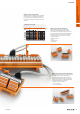
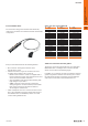
Digital input/output interfaces (H System)
The digital input/output interfaces have been designed using
a ribbon cable connector suitable for the majority of signals
coming from the PLC. In addition, the pre-assembled cables
are designed using a cross-section of 0.25 mm
2
and have a
cover that guarantees complete and safe fastening with the
interface connector.
The range has been designed for 8,12,16 and 32 signals
in tension clamp or screw connection and you can choose
additional functions including:
• LED
• Fusible
• Interruptor
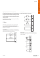
Additionally, sensors/actuators can be connected using
1-, 2-, or 3-wire techniques; this way, the space that is
usually needed for connecting the common power supply
points, which are normally connected via additional
terminals, is not required.
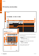
1-wire system:
In eld components, one of the wires is connected to the
interface while the other is connected to a common power
supply point (for example a terminal block).
0.0
0.1
0.7
+
–
+
–
2-wire system:
The 2 wires of the eld element are connected to the
interface with power bus in one of them.
+
–
0.0
0.1
0.7
C
C
C
C
+
–
3-wire system:
The interface is designed for 3 wire eld components, with
one for positive, one for negative and one for the signal that
is sent to the PLC.
+
–
+
+
+
+
–
–
–
–
1.7
0.1
0.0
A
A.52690170000
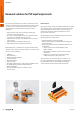
Universal solutions for PLC input/
output cards