
Brochure/Catalogue


E
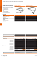
Isolated Interfaces and solutions for general
applications
E.50 2690170000
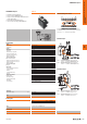
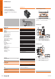
TERMSERIES adapters
• Suitable for input and output logic
• Version for 6.4mm TERMSERIES base
• Supply connections (PUSH IN) in double execution for
supply voltage bridging
• User-friendly and unmistakable marking
• 20-pin connecting plug according to DIN EN 60603-13
Technical data
Supply
Supply voltage
Status display
Signals
Rated voltage
Voltage, max.
Rated current (per signal path)
Current (per signal path), max.
Total current of all signals, max.
Number of signal paths
Connection data (supply)
Wire connection method
Clamping range, rated connection, min.
Clamping range, rated connection, max.
Number of terminals
Connection data (signal)
Plug type
General data
Ambient temperature (operational)
Storage temperature
Humidity
UL 94 flammability rating
Approvals
Insulation coordination
Pollution degree
Overvoltage category
Impulse withstand voltage
Rated voltage
Protection degree
Dimensions
Depth x width x height mm
Note
Ordering data
Note
Accessories
Note
TIAL F20
9'&
²
²
24 V DC ± 20 %
Green LED
24 V DC
30 V DC
60 mA
1 A
1 A
16
PUSH IN
0.13 mm²
1.5 mm²
4 (+,+,−,−)
20-pole plug according to DIN EN 60603-13, long locking lever
-40 °C...60 °C
-40 °C...85 °C
5...95% (indoor), T
u
= 40°C, no condensation
V-0
CE; cULus; GL
2
III
1.5 kV
32 V
IP 20 in installed condition
62 / 102 / 43
Type Qty. Order No.
TIAL F20 1 1463550000
Suitable for 6.4mm wide TERMSERIES base
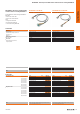
The potential change-over switch is located between contact rows of
the TERMSERIES adaptor. It is used to switch the potential of the lower
contact row to “+” or “-” potential of the supply voltage.
14
A1 +
A2 -
1122770000
TRS 24VDC 1CO
24
V
24V
1114 12
A2
NO
11
12
COM
NC
14 11 A1
A2
TOSTRS
A1
Figure 1a
Figure 1b
14
A1 +
A2 -
1122770000
TRS 24VDC 1CO
24V
24V
1114 12
A2
NO
11
12
COM
NC
14 11
A1 A2
TOSTRS
A1
Figure 2a
Figure 2b
Figure 2a:
Positive-switching logic: Potential change-over
switch to “+”, installation on output (11/14).
Figure 2b:
Negative-switching logic: Potential change-over
switch to “-”, installation on output (11/14).
Potential change-over switch
Installation input
Installation output
Figure 1a:
Positive-switching logic: Potential change-over
switch to “-”, installation on
24 V DC input (A1/A2).
Figure 1b:
Negative-switching logic: Potential change-over
switch to “+”, installation on
24 V UC input (A1/A2).
TERMSERIES adapters