
Brochure/Catalogue


for EMR
for SSR
Pollution severity level Pollution (contamination) includes any foreign material – whether it is solid, liquid
or gaseous (ionised gas) – which is capable of inuencing the surface resistance
of the insulating material. The standard denes four degrees of pollution. Their
numbering and classication is based on the quantity of the contaminant or the
frequency with which the contaminant reduces the dielectric strength and/or
surface resistance.
Pollution degree 1:
• there is no contamination or only dry occurrences of non-conductive pollution.
The pollution has no inuence.
Pollution degree 2:
• there is only non-conductive pollution. Temporary occurrences of conductivity
caused by condensation may also occur.
Pollution degree 3:
• conductive pollution or dry, non-conductive pollution that can become
conductive due to condensation is likely to occur.
Pollution degree 4:
• the contamination leads to continual conductivity which can be caused by
contaminants such as conductive dust, rain or snow.
x x
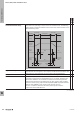
Positively driven contacts Relays with positively driven contacts according to EN 61810-3 are characterised
by the fact that, due to a mechanical guide, the NO and NC contacts of a relay
cannot be closed at the same time.
Design differences compared to relays with standard contacts:
In relays with positively driven contacts, some components within the relay have
a more heavy-duty design. This is the case for components such as the contact
springs and the armature.
This is in order to reduce the possibility of a dangerous failure. However, it also
means that the coils in these relays need to be stronger in order to move the
larger or heavier parts. As a result, these types of relays have up to twice the
power consumption compared to standard relays.
In addition, there is more insulation between the input and output and between
the output channels in relays with positively driven contacts compared to
standard relays of the same size.
To use relays with positively driven contacts for safety applications, at least one
of the relay’s NO contacts and one of its NC contacts must be integrated into the
circuit design. The NO contact of the rst channel then switches the function in
the safety application and the NC contact of a second channel gives a feedback
signal to the control unit. This means that if one of the NO contacts welds, for
example, the following function step of the application cannot be initiated and
the circuit is stopped because the NC contact cannot give a feedback signal due
to the fact that the NO is welded.
The standard EN 61810-3 describes the requirements for relays with positively
driven contacts.
• Type A: Type A relays only have NO and NC contacts
• Type B: Type B relays have CO contacts; in applications where the positively
driven contact function is to be used, only the NO or NC contacts of a
CO contact may be used.
x
EMR = Electromechanical relay
SSR = Solid-state relay
Glossary: Relay modules and Solid-state relays
W
Technical appendix/Glossary
W.30 2737920000