
Brochure/Catalogue


for EMR
for SSR
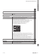
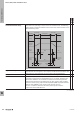
Standardised labelling of
connections
Connection designation according to EN 50005:
The connections are dened by a two-digit code:
A1 and A2 are used for the connections of the input or the coil
For inputs of time relays which have connections for triggering the time function
(control input), these are designated B1.
For the connections at the output, the rst number indicates the respective
output channel and the second number the function.
The following examples are given for a 1-channel output:
NO contact: 13, 14
NC contact: 11, 12
CO contact: 11, 12, 14 (connection 11 is the common contact, i.e. the root)
For relays with more than one output channel, the rst number for the respective
contact set is exchanged.
For example, for a 2 changeover relay: 11, 12, 14 for the rst CO contact and 21,
22, 24 for the second CO contact
For outputs of timing relays, the function numbers change from .1 to .5, from .2
to .6 and from .4 to .8.
The rst CO contact is therefore designated 15, 16 and 18 for timing relays.
Connection designation according to IEC 67:
Common in the USA. In this case, the connections are numbered consecutively.
A relay with 4 CO contacts therefore has the numbers 1 to 14.
It should be noted that numbers 11, 12 and 14 appear in both connection
marking systems but have different functions.
Instead of the coil connection markings A1 and A2, the terminal markings A and
B are also commonly used.
However, the connection designations according to IEC 67 are being used
less and less frequently, which is why they are seen on fewer and fewer relay
modules.
x x
Status indicator (input) Unless otherwise described, the status indicator for relay modules and solid-state
relays indicates the presence of a control voltage at the input.
It does not indicate the state of the output and may deviate from the state of the
output in the following cases:
• Welded/defective switching elements
• Interference radiation or residual voltages on the control lines
At ambient temperatures > 50°C, the luminosity and service life of the LED may
be reduced.
The function of other status indicators is described in the respective
documentation.
x x
Storage temperature The permitted ambient temperature, related to a specic relative humidity level,
for which the product should be stored while in a current-free state.
x x
EMR = Electromechanical relay
SSR = Solid-state relay
W
Technical appendix/Glossary
W.372737920000
Glossary: Relay modules and Solid-state relays