IECEE OD-2020-F1:2017 © IEC 2017 TRF Template Ed.1.0 2017-05-17 Test Report issued under the responsibility of: TEST REPORT IEC 61984 Connectors – Safety requirements and tests Report Number ............................... : 250148-TL6-1 Date of issue................................... : 2018-06-26 Total number of pages .................. : 23 Name of Testing Laboratory preparing the Report ...................
Page 2 of 23 Report No.: 250148-TL6-1 Test item description ....................... : Connector (COC) Trade Mark ........................................ : Manufacturer .................................... : Weidmüller Interface GmbH & Co. KG; Klingenbergstraße 16; 32758 Detmold; Germany Model/Type reference ...................... : BCZ 3.81 Buchsenteil / female part; SC 3.81 Stiftteil / male part Ratings ..............................................
Page 3 of 23 Report No.
Page 4 of 23 Report No.: 250148-TL6-1 Copy of marking plate: The artwork below may be only a draft. The use of certification marks on a product must be authorized by the respective NCBs that own these marks. BCZ 3.81 SC 3.81 TRF No. IEC61984C Testreport-250148-TL6-1.DOCX VDE File No.
Page 5 of 23 Report No.: 250148-TL6-1 Test item particulars ..................................................: Classification of installation and use ......................: Build in Supply Connection .....................................................: .......................................................................................: Possible test case verdicts: - test case does not apply to the test object ........... : N/A - test object does meet the requirement .................
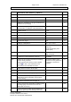
Page 6 of 23 Report No. 250148-TL6-1 IEC 61984 MECHANICAL TEST GROUP A (TABLE 10) A1 VISUAL EXAMINATION: IEC 60512 Test 1a 6.2.2 Marking indelible and easily legible P Minimum marking on the connector a) trademark P Markings a) trademark and b) type identification on smallest unit of packaging P All other markings (c – k) given in the technical documentation or catalogue of the manufacturer P 6.2.3 c) Rated current ..................................................
Page 7 of 23 Report No. 250148-TL6-1 IEC 61984 provisions in the end-use product DIMENSIONAL EXAMINATION: IEC 60512 6.19 Clearances and creepage distances according to IEC 60664. see table 0.2 Connector dimensions comply with the DS or manufacturer’s specification. A2 DURABILITY OF MARKING 7.3.
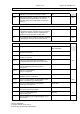
Page 8 of 23 Report No. 250148-TL6-1 IEC 61984 Minimum cross- section according to Table 1 ..... : mm² 6.5.4.2 With regard to design and type of construction, the protective conductor terminations are at least equivalent to the other terminations according to clause 6.: A5 INTERLOCK 7.3.4 The specimens are engaged by hand over their full engagement distance. All other contacts are wired in series. The interlock contacts “make last and break first”, before any other contact does. N/A 6.
Page 9 of 23 Report No. 250148-TL6-1 IEC 61984 A7 CONTACT RETENTION IN INSERT: IEC 60512 Test 15a Test load shall be three times the specified insertion force (mating) of one contact or the specified insertion force of one contact plus 50 N, whichever is less. Minimum test load 20 N. insertion force of one contact: 3,4 N Test load 20 N — VISUAL EXAMINATION: IEC 60512 Test 1a 6.18.2 Contacts safety retained P No axial displacement likely to impair normal operation P A8 CABLE CLAMP: IEC 60512 6.
Page 10 of 23 Report No. 250148-TL6-1 IEC 61984 A9 MECHANICAL STRENGTH IMPACT (Only free Connectors and CBC): IEC 60512 Test 7b — Dropping cycles: 8 positions in 45° steps Dropping height .................................................. : mm — VISUAL EXAMINATION: IEC 60512 Test 1a 6.18.1 No damage likely to impair safety N/A 6.18.
Page 11 of 23 Report No. 250148-TL6-1 IEC 61984 B4 FINAL MEASUREMENTS (CONTACT RESISTANCE): IEC 60512 Test 2b Test current ........................................................ : 1A R2 1,5 R1 See appended table B4.1 P a) Impulse withstand voltage ............................. : -- b) r.m.s. withstand voltage ................................. : 1,39kV 6.13 No breakdown or flashover occurred See appended table B4.
Page 12 of 23 Report No. 250148-TL6-1 IEC 61984 THERMAL TEST GROUP C (TABLE 12) C1 7.3.7 6.16 TEMPERATURE RISE TEST: IEC 60512 Test 5A Test conductor length according Table 7 ............ : Female part: 250 mm Male part: direct bridged Test conductor cross-section .............................. : 1,5 mm² Mated specimen ................................................. : BCZ 3.81 + SC 3.81 Test current ........................................................
Page 13 of 23 Report No. 250148-TL6-1 IEC 61984 D3 DRY HEAT: IEC 60512 Test 11i Mated specimen .................................................. : BCZ 3.81 + SC 3.81 — Test duration ...................................................... : 7 days — Upper temperature limit ...................................... : 120°C — VISUAL EXAMINATION: IEC 60512 Test 1a 6.6.3 Sufficient contact pressure through insulation N/A 6.8 / 6.
Page 14 of 23 Report No. 250148-TL6-1 IEC 61984 DEGREE OF PROTECTION TEST GROUP E (TABLE 14) E1 PROTECTION AGAINST ELECTRIC SHOCK Unenclosed connectors (for use inside an enclosure): 5.4 c1) COC classified as IP0X, no test required IP00 P 6.4.2.2 5.4 c2) COC Hand back safety (IP1X or IPXXA) 50 mm sphere pressed with 20 N against mated specimen. No live parts accessible. N/A 6.4.2.3 5.4 c3) COC Finger safety (IP2X or IPXXB) Jointed test finger pressed with 20 N against mated specimen.
Page 15 of 23 Report No. 250148-TL6-1 IEC 61984 E3 DEGREE OF PROTECTION IP CODE: IEC 60529 7.3.6.3 Tests for IP Codes higher than IP2X or IPXXB 6.12 7.3.7.1 IP code according to IEC 60529 in mated condition or according manufacturers conditions ............... : IP — Maximum and minimum cross-section wiring or cable diameter connected ................................... : mm² / mm — mm² / mm 7.3.7.
Page 16 of 23 Report No. 250148-TL6-1 IEC 61984 B1 TABLE: Initial measurements (Contact resistance) Test current ...................................................................... : — 1A Test sample Contact 1 2 3 PE 1 U1 [mV] 1,4 2,6 1,3 -- R1 [m] 1,4 2,6 1,3 -- Contact 1 2 3 PE U1 [mV] 1,2 1,4 1,4 -- R1 [m] 1,2 1,4 1,4 -- Contact 1 2 3 PE U1 [mV] 1,2 1,3 1,2 -- R1 [m] 1,2 1,3 1,2 -- 2 3 supplementary information: BCZ 3.81 + SC 3.81 B4.
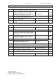
Page 17 of 23 Report No. 250148-TL6-1 IEC 61984 B4.2 TABLE: Dielectric strength (mated specimen) Test voltage applied between: a) Impulse withstand voltage applied b) r.m.s withstand voltage applied Breakdown / flashover (Yes/No) Contact – Contact -- 1,39 kV No Contact – Earth -- -- -- Contact – Surface -- -- -- supplementary information: BCZ 3.81 + SC 3.81 C1 TABLE: Temperature rise test Ambient temperature (°C) ...................................
Page 18 of 23 Report No. 250148-TL6-1 IEC 61984 D1 TABLE: Initial measurements (Contact resistance) — Test current ................................................................................. : 1 A Test sample Contact 1 2 3 PE 1 U1 [mV] 0,77 1,0 1,2 -- R1 [m] 0,77 1,0 1,2 -- supplementary information: BCZ 3.81 + SC 3.81 D5 TABLE: Final measurements (Contact resistance) Test current ...............................................................................
Page 19 of 23 Report No. 250148-TL6-1 IEC 61984 0.1 TABLE: Characteristic features Example ...................................
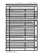
Page 20 of 23 IEC 61984 0.1 TABLE: Characteristic features Operating cycles 10 50 100 500 1000 2000 5000 X Bendings According manufacturer’s: 25 10 50 100 500 1000 2000 5000 20000 X Upper temperature limit According manufacturer’s: N/a 70°C 85°C 100°C 125°C X Lower temperature limit According manufacturer’s: 120°C -10°C -25°C -40°C -55°C 0°C X TRF No. IEC61984C Testreport-250148-TL6-1.DOCX VDE File No. 257500-1431-0045/250148 According manufacturer’s: -50°C Report No.
Page 21 of 23 IEC 61984 0.
Page 22 of 23 Report No. 250148-TL6-1 IEC 61984 TABLE: Clearance and creepage distance measurements Pitch 5 mm 0.2 Type / Shell-size / etc. .............. : BCZ SC Clearances measured .............. : 3,9 mm 3,1 mm Creepage distances measured : 3,9 mm 4,4 mm Impulse withstand voltage [kV] . : 2,5 Test voltage [kV] ....................... : 1,39~ Clearances required ................. : 1,5 mm Isolation material group ............ : I I Rated voltage [V] ......................
Page 23 of 23 Report No. 250148-TL6-1 IEC 61984 TABLE: IEC 89/336/CD / Ball-pressure test 0.3.3 Specimen Part --- Material Ball-pressure test Materialthickness [mm] Colour [C°] Measured [mm] Required [mm] Result --- --- --- --- --- --- --- Supplementary information: TABLE: IEC 60695-2-2 / Needle-flame test 0.3.