
Brochure/Catalogue


10
Design and processing recommendations
With our expertise, you can realise your ideas efciently
For optimum soldering results in the SMT process we recommend the following parameters for our THR components:
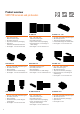
Pin header
Pins Inner diameter of
solder eyelet
D [mm]
Outer diameter of
solder eyelet
D
A
[mm]
Stencil aperture
diameter
D
SI
[mm]
Solder pin diameter
d [mm]
Solder pin
length
L [mm]
S2C-SMT 3.50 &
S2L-SMT 3.50
4–36 1.30
+0,1
2.10 1.90 1.0, octagonal 1.50
SL-SMT 3.50 2–8 1.40
+0,1
2.30 2.10 1.2, octagonal 1.50
SL-SMT 3.50 LF/RF
SL-SMT 3.50
2–8
9–24
1.50
+0,1
2.30 2.10 1.2, octagonal 1.50
SC-SMT 3.81 2–16 1.30
+0,1
2.10 1.90 1.0, octagonal 1.50
SL-SMT 5.00/5.08 2–8 1.40
+0,1
2.30 2.10 1.2, octagonal 1.50
SL-SMT 5.00/5.08 LF/F
SL-SMT 5.00/5.08
2–8
9–24
1.50
+0,1
2.30 2.10 1.2, octagonal 1.50
LSF-SMT 3.xx
LSF-SMT 5.xx
LSF-SMT 7.xx
2–12
2–8
2–6
1.10
+0,1
1.90 1.70 0.9 (0.35 x 0.8) 1.50
Stencil thickness D
S
[µm]
120–180 (continuous for all product families listed)
Solder paste grain size [µm] 20–40 = Type 3
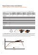
For our SMT components, we recommend the following reow soldering prole, illustrated here with a typical characteristic
and process boundaries. In the preheating phase, the PCB and components are preheated while the solder paste is activated.
Above a temperature of 217 °C to 221 °C, the solder fuses and joins the components to the connectors on the board. The
temperature is maintained at 245 °C to 254 °C for between 10 and 45 seconds in order to ensure a secure connection. During
the cooling period the solder hardens. Stress cracks as a result of excessively rapid cooling must be avoided.
300
250
217
200
150
100
50
0
0 50 100 150 200 250 300 350
Time [sec]
Temperature [°C]
preheating
Melting point lead-free solder paste
Cooling rate:
< 6 °K/s
180 °C
190 °C
235 °C
245 °C
254 °C
approx.
60 s > 217 °C
Continuous line: Typical process
Dotted line: Process limits
Heating rate: < 3 °K/s
d
d
H
D
D
A
D
SI
D
S