SIL Safety Manual Manual Monitoring Safety Relay SCS 24VDC P2SIL3DSES
Foreword Revision history Version Date Change 0.0 12/2012 First Edition 1.0 04/2013 Chapter 3.1 and 3.2 updated 2.0 08/2013 Tables 2 to 4 updated 3.0 02/2018 Page 5, TÜV Logo updated Page 17, deleted Contact address Weidmüller Interface GmbH & Co. KG Klingenbergstraße 16 32758 Detmold Germany Phone Fax E-mail Internet 1422650000/03/02-2018 +49 (0) 5231 14-0 +49 (0) 5231 14-2083 info@weidmueller.com www.weidmueller.
Content 1 1.1 Scope and standards............................................................................................. 5 Scope........................................................................................................................ 5 1.2 Abbreviations............................................................................................................ 5 2 2.1 Device description and application......................................................................
Scope and standards 1 Scope and standards 1.1 Scope 1.2 This safety manual applies to SIL3 relays from Weidmüller‘s SAFESERIES for the following items produced after 11/2012: SCS 24VDC P2SIL3DSES 1319270000 SIL3 relays in the SCS 24VDC P2SIL3DSES series from Weidmüller Interface GmbH & Co KG Klingenbergstraße 16 32758 Detmold Germany have been certified by TÜV NORD CERT GmbH Certification Body Maschinery Notified Body 0044 Langemarckstr. 20 45141 Essen Germany according to EN 61508 SIL3.
Scope and standards FMEDA (Failure Mode, Effects and Diagnostic Analysis): Systematic way to identify and evaluate the effects of different component failure modes, to determine what could eliminate or reduce the chance of failure, and to document a system in consideration.
Device description and application 2 Device description and application 2.1 General The safety relay in the SAFESERIES product family is certified according to DIN EN 61508 / SIL3. It is used for safely energising (ETS = energised to safe) and de-energising (DTS = de-energised to safe) system components in process industry applications. It also meets the requirements of EN 61508, SIL3 for a “low demand mode” and “high demand mode”. 2.
Device description and application 2.
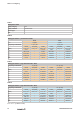
Notes on configuring 3 Notes on configuring 3.1 Low demand mode of operation The SIL3 relays from the SAFESERIES are used in low demand mode, when their demand frequency is no more than one times per year and no more than double the repeated testing frequency (refer to DIN EN 61508-4, 3.5.12). The corresponding parameter for DTS applications is the value PFDavg = 2.11 × 10⁻⁸, which is valid for a testing interval Tproof of 12 years.
Notes on configuring Table 1 Safety basic data Safety category SIL3 Safety standard DIN EN 61508 Device type A HFT 1 Table 2 Safety parameters „low demand mode“ DTS Tproof Frequency of demands 1001D PFDavg 1.78 × 10 -8 ETS 12 years 3 years 1× per year 1× per year Complete 1002D 2.11 × 10 3.30 × 10 -8 1001D -9 1.51 × 10 -5 Complete 1002D 1.75 × 10 2.37 × 10⁻⁶ -5 λSD 0 FIT – 0.11 FIT 0 FIT – 2.59 FIT λSU 126.74 FIT – 22 FIT 88.14 FIT – 12.69 FIT λDD 0.
Notes on configuring 3.3 Types of malfunctions A safe failure is not able to render a technical safety system dangerous or non-functional. The SIL3 relay passes to a predefined safe state. A dangerous, undetected failure has the potential to render a technical safety system dangerous or nonfunctional. The SIL3 relay does not pass to a predefined safe state. 1422650000/03/02-2018 3.4 Test intervals The test interval is the time between complete repeated tests.
Mounting and installation 4 Mounting and installation The operating instructions for the SIL3 relay with the order number IS SCS 24VDC P2SIL3DSES 1412610000 must be made available. The instructions, constraints and limitations contained in these instructions must be taken into consideration when installing and operating the SIL3 relay. The output circuit is protected with a miniature device fuse (GS fuse). The fuse is accessible on the front side of the housing.
Periodic inspections 5 Periodic inspections Periodic functional inspections are used to discover non-visible and dangerous faults which cannot be detected. It is therefore important to check the functionality of the SIL3 relay with the proper frequency. The inspections should be carried out so that the flawless operation of the safety functions in conjunction with components can be proven. The operator must determine the type of tests and the proper time intervals.
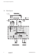
Periodic inspections 5.1 Functional check The existing relays are applied diversely (separately) and interact together with the respective switch output. For testing these relays, terminals X1, X2 and X3 are available. Test circuit 2 DTS Output ETS Output Ω Ω The testing mode is indicated by LEDs in accordance with NAMUR NE44.
Periodic inspections Test circuit 4 Test circuit 5 DTS Output ETS Output DTS Output ETS Output Ω Ω Ω Ω + + + - - + 24 V DC Input + 24 V DC Test Input 2 + 24 V DC Test Input 1 Test circuit Input A1/A2 Test Input 1 X1/X3 Test Input 2 X2/X3 DTS- Output 13/14, 13/F ETS- Output 23/24 LED red „TEST 1” LED red „TEST 2” LED yellow „RELAY OUTPUT” 1 NC 0 V DC 0 V DC : : OFF OFF OFF 2 NC 24 V DC NC : 0Ω blinking OFF OFF 3 NC NC 24 V DC : 0Ω OFF blinking OFF 4
Technical safety values 6 Technical safety values 6.1 Assumptions • The max. allowable ambient temperature is 50 °C. • The environmental conditions correspond to the average industrial environment. 16 • The specifications in the data sheet and the operating instructions should not be exceeded.
www.weidmueller.com Weidmüller Interface GmbH & Co. KG Klingenbergstraße 16 32758 Detmold Germany Phone +49 (0) 5231 14-0 Fax +49 (0) 5231 14-292083 E-Mail info@weidmueller.com Internet www.weidmueller.