Montageanleitung PV Feldsteckverbinder WM4 C Gehäusesteckverbinder BOX WM4 C Installation instructions PV Field connector WM4 C PV Box connector BOX WM4 C
Inhalt Content Verwendete Symbole Allgemeine Sicherheitshinweise Sicherheitshinweise für die Montage Bestimmungsgemäßer Gebrauch Empfohlendes Werkzeug Steckverbinder montieren Steckverbinder öffnen Technische Daten Bestelldaten 2 3 3 3 3 4 7 8 9 Symbols used General safety notes Safety notes for installation Intended use Recommended tools Installing the plug-in connectors Disconnecting the plug Technical data Order data 10 11 11 11 11 12 15 16 17 Verwendete Symbole Dieses Symbol warnt vor Gefahren dur
Allgemeine Sicherheitshinweise –– Die elektrischen Verbindungen dürfen nicht unter Last gesteckt und getrennt werden. –– Die Produkte dürfen nur von Elektrofachkräften installiert werden. –– Die PV-Steckverbinder dürfen nicht in direkten Kontakt mit Produkten oder Medien (inklusive Gase) geraten, welche Benzin, Kerosin oder Weichmacher enthalten. Sicherheitshinweise für die Montage WARNUNG Gefährliche Spannung! Je nach Lichteinstrahlung kann vom Modul erzeugte Spannung anliegen.
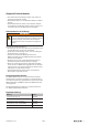
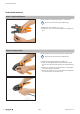
Steckverbinder montieren Steckverbinder montieren Schritt 1: Kabel konfektionieren Benötigtes Werkzeug: Multi-Stripax PV (1190490000) Beachten Sie die Anleitung zum Werkzeug. ▶▶ Abisolieren Sie das Kabel (8 ± 1 mm). ▶▶ Stellen Sie sicher, dass keine Einzellitzen beschädigt werden. Schritt 2: Kontakte crimpen Benötigtes Werkzeug: Crimpwerkzeug PV (1222870000) Beachten Sie die Anleitung zum Werkzeug. ▶▶ Stellen Sie den Positionsgeber auf „WM4“ ein.
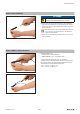
Steckverbinder montieren Schritt 3: Leiter anschließen ACTHUNG Achten Sie darauf, dass Sie keine WM4-Kontakte in die WM4 C-Steckverbindergehäuse stecken! ▶▶ Führen Sie den gecrimpten Kontakt in das zugehörige Gehäuse gleichmäßig bis zum Endanschlag ein. Achten Sie darauf, dass der gecrimpte Kontakt hörbar mit einem “Klick” verrastet. Bei Kabeln mit dem maximalen Außendurchmesser von 7 mm kann es notwendig sein, die Überwurfmutter zurückzudrehen.
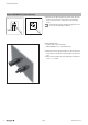
Steckverbinder montieren Schritt 4 (BOX WM4 C): Gehäuse montieren ▶▶ Bereiten Sie die Montageöffnung gemäß den nebenstehenden Zeichnungen vor. Wenn Sie einen Rotationsschutz erreichen wollen, beachten Sie die linke Bohrskizze. Achten Sie darauf, dass die Bohrung gratfrei ist, bevor Sie mit der Montage fortfahren. Rotationsschutz / Anti-rotation protection ∅ ∅ 12 .1 .1 12 5.2 ±0.05 .05 .
Steckverbinder öffnen Schritt 5: Steckverbinder schließen ▶▶ Stecken Sie das Stiftgehäuse in das Buchsengehäuse bis die Rasthaken einschnappen. ▶▶ Prüfen Sie die korrekte Verrastung durch leichtes Ziehen. Steckverbinder öffnen WARNUNG Gefährliche Spannung! Je nach Lichteinstrahlung kann vom Modul erzeugte Spannung anliegen. Die elektrischen Verbindungen dürfen nicht unter Last gesteckt und getrennt werden! Die Gehäuseteile des Steckverbinders können ohne Werkzeug getrennt werden.
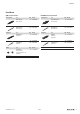
Technische Daten Technische Daten WM4 C BOX WM4 C Zulässiger Temperaturbereich –40 °C … +85 °C Schutzart (gesteckt / ungesteckt) IP65 / IP2x Bemessungsstrom nach TÜV 35 A Bemessungsspannung 1.500 V DC (IEC) Schutzklasse Bauart Anzugsdrehmoment Max. Wandstärke Anschließbare Kabel II einpoliger, nicht wiederverwendbarer, freier Steckverbinder ∅ 5,5 ... <6,0 mm: 2,0 Nm ± 0,2 / ∅ 6,0 ... 7,0 mm: 1,5 Nm ± 0,2 Metallgehäuse: 6 mm; Kunststoffgehäuse: 10 mm Kabel nach Standard 2 PfG1169/08.
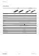
Bestelldaten Bestelldaten WM4 C Feldsteckverbinder Buchsengehäuse Typ BUGH WM4 C BT Buchsengehäuse BUKO WM4 C BT BUKO WM4 C RL Buchsenkontakt Stiftgehäuse Typ SFGH WM4 C BT Stiftgehäuse SFKO WM4 C BT SFKO WM4 C RL Stiftkontakt Zubehör Typ VSSO WM4 C Staubschutzkappe universell für Buchsen- und Stiftgehäuse BOX WM4 C Gehäusesteckverbinder VPE* Best.-Nr. 100 1530690000 Buchsengehäuse 100 1530670000 1500 1530770000 VPE* Best.-Nr. 100 1530700000 Best.-Nr.
Content Symbols used General safety notes Safety notes for installation Intended use Recommended tools Installing the plug-in connectors Disconnecting the plug Technical data Order data 10 11 11 11 11 12 15 16 17 Symbols used This symbol cautions against danger caused by hazardous voltage. This symbol cautions against danger that may result in material damage. This symbol advises you to regard this and other documentations if applicable.
General safety notes General safety notes –– The electrical connections must not be disconnected and plugged under load. –– The products may only be installed by electrically skilled persons. –– The PV plug-in connectors must be kept away from products or mediums (including gases) that contain petrol, kerosine or plasticizer. Safety notes for installation WARNING Hazardous voltage! The electrical connections must not be disconnected and plugged under load.
Installing the plug-in connectors Installing the plug-in connectors Step 1: Assembling the cables Required tool: Multi-Stripax PV (1190490000). Please regard the tool’s documentation. ▶▶ Strip the cable to a length of 8 ±1 mm. ▶▶ Take care not to damage individual strands of the cable. Step 2: Crimping the contacts Required tool: Crimping tool PV (1222870000) Please regard the tool’s documentation. ▶▶ Set the locator to “WM4”.
Installing the plug-in connectors Step 3: Connecting the line ATTENTION ▶▶ Do not insert a WM4 contact for the WM4 C connector housing! ▶▶ Insert the crimped contact evenly into the housing until the contact has reached its end position and a “click” can be heard. If using cables with the maximum external diameter of 7 mm it may be neccessary to turn back the union nut. ▶▶ Check that the fastening is correct by gently pulling the cable.
Installing the plug-in connectors Step 4 (BOX WM4 C): Assembling the housing ▶▶ Prepare the assembly opening according to the adjacent drawings. If you want to achieve the anti-rotation protection, please regard the left hand drawing. Please make sure that the opening is free of burrs before you continue the assembly. Rotationsschutz / Anti-rotation protection ∅ ∅ 12 .1 .1 12 5.2 ±0.05 .05 .
Disconnecting the plug Step 5: Connecting the plug ▶▶ Plug the male pin housing into the female socket housing until the latching hooks snap into place. ▶▶ Check that the fastening is correct by gently pulling. Disconnecting the plug WARNING Hazardous voltage! The electrical connections must not be disconnected and plugged under load. Depending on the light intensity, voltage, generated by the module, may be present! The housings of the plug can be separated without any tool.
Technical data Technical data WM4 C Permissible temperature range BOX WM4 C –40 °C … +85 °C Protection degree (mated / unmated) IP65 / IP2x Rated current according to TÜV 35 A Rated voltage 1.500 V DC (IEC) Protection class II Construction type unipolar, not reuseable, free connector Tightening torque ∅ 5.5 ... <6.0 mm: 2.0 Nm ± 0.2 / ∅ 6.0 ... 7.0 mm: 1.5 Nm ± 0.2 Max.
Order data Order data WM4 C Field connector Female socket housing BOX WM4 C Box connector Type BUGH WM4 C BT Female socket housing BUKO WM4 C BT BUKO WM4 C RL Female socket contact Male pin housing Type SFGH WM4 C BT Male pin housing SFKO WM4 C BT SFKO WM4 C RL Male pin contact Accessories Type VSSO WM4 C Universal dust cap for female socket housing and male pin housing Pack. unit* Order No. 100 1530690000 Female socket housing 100 1530670000 1500 1530770000 Pack. unit* Order No.
Weidmüller Interface GmbH & Co. KG Klingenbergstraße 16 D-32758 Detmold T +49 5231 14-0 F +49 5231 14-292083 www.weidmueller.com 2454640000/02/07.