
Brochure/Catalogue


B
B.66 2737920000
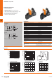
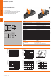
RCI-KITP with PUSH IN connection
1 CO contact AC/DC coil
'&9HUVLRQ
$&9HUVLRQ
&LUFXLWGLDJUDP
$
$
$
$
Load side
Rated switching voltage / Continuous current 250 V AC / 16 A
(1
Max. switching voltage, AC 400 V
Inrush current 30 A / 4 s
Min. switching power 1 mA @ 24 V, 10 mA @ 12 V, 100 mA @ 5 V
Contact type 1 CO contact with test button (AgNi 90/10)
Mechanical service life AC coil 5 x 10
6
switch. cycles, DC coil 10 x 10
6
switch. cycles
Max. switching frequency at rated load 0.1 Hz
General data
Ambient temperature (operational) -40 °C...70 °C
Storage temperature -40 °C...70 °C
Humidity 40 °C / 93 % rel. humidity, no condensation
Approvals CE; DNVGL; EAC
Insulation coordinates
Rated voltage 250 V
Impulse withstand voltage 5 kV (1.2/50 µs)
Dielectric strength, Input/Output 5 kV
eff
/ 1min
Dielectric strength of neighbouring contacts
Dielectric strength to mounting rail
Creepage and clearance distance input – output ≥ 8 mm
Overvoltage category III
Pollution degree 2
Dimensions PUSH IN
Clamping range (nominal / min. / max.) mm² 1.5 / 0.75 / 1.5
Depth x width x height mm 69.6 / 15.8 / 98
Note
1) For full continuous current (16 A), relay connections 11 - 21, 12 - 22 and 14 - 24
must be bridged. Further technical data can be found at catalog.weidmueller.com
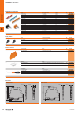
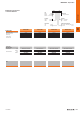
Dimensioned drawing
Operating voltage range [DC]
Coil voltage [U/Un]
Ambient temperature [°C]
Operating voltage range [AC]
Coil voltage [U/Un]
Ambient temperature [°C]
Switching current [A]
Switching operations
Electrical endurance
250 V AC Resistive load
Switching voltage [V DC]
Switching current [A]
DC load breaking capacity
Resistive load
Derating curve
Load current [A]
* For full continuous current (16 A), socket connections
11–21, 12–22 and 14–24 must be bridged.
dense packing
10
7
10
6
10
5
10
4
0 2 4 6 8 10 12 14 16
1 contact
300
200
100
50
40
30
20
10
0.1 0.2 0.5 12 51020
69.6 mm
98 mm
0 A
16 A
Un Rated coil voltage
3.0
2.6
2.2
1.8
1.4
1.0
0.6
0 +20 +40 +60 +80 +100
Un Rated coil voltage
0 A
16 A
2.2
2.0
1.8
1.4
1.2
1.0
0.8
0.6
1.6
0 +20 +40 +60 +80 +100
16
14
12
10
8
6
4
0 +20 +40 +60 +80 +100
Applications
Technical data
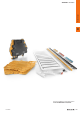
• Mounted kit consisting relay, socket and retaining clip
• 100 % function tested
• 100 % check of the dielectric strenght between input - output
• Optional test button with mechanical status indicator
• Bright status LED (AC coil: red / DC coil: green)
• Identification of coils (AC red / DC blue)
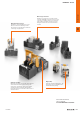
Universal range
RIDERSERIES – relay modules