
Brochure/Catalogue


In our selection tables we specied the maximum
recommended switching currents for inductive loads without
protective circuits. If you want to increase the service life
of the contacts, you must equip the relay contacts with an
effective protective circuit.
The protective circuit on the coil side of a relay module can,
for example, be implemented with an integrated or addition-
ally pluggable freewheeling diode. However, this only
protects the controlling periphery from the voltage peaks
that occur in the coil of the relay module. The relay contact
is usually not sufciently protected against the voltage peaks
of the inductive load to be switched, although with optimum
dimensioning almost the same values for switching capacity
or switching cycles can be achieved as with resistive load.
The largest reduction factor for the service life of a relay
contact is the arc generated during switching off inductive
loads. It is caused during the switching process by the
energy stored in the coil and can destroy the contact through
material evaporation and material migration.
With DC voltage and standing arc, the relay can even fail
during the rst switching cycle. Voltage peaks caused by
electric arcs can reach values up to several 1,000 volts.
A protective circuits must be used to suppress the formation
of electric arcs.
In the following, we will explain the correct installation of the
protective circuit and the effectiveness of the most common
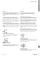
types of protective circuit. There are various ways to install
an effective protective circuits. For example, the protective
circuit can be mounted either parallel to the relay contact or
parallel to the load.
However, the protective measure should always apply
directly to the source of the fault. Therefore, the protective
circuit of the load is preferable to the circuit of the contact.
Advantages of a protective circuit at the load:
• When the contact is open, the load is still galvanically
isolated from the operating voltage
• The switch-off peaks of the load cannot be coupled into
the control lines running in parallel
Effective protection of outputs of relay modules and solid-state relays
Selection criteria for the protective suppressor circuit of inductive loads
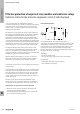
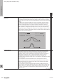
Free-wheeling diodes
U
D
load
+
–
U
S
12
t
Free-wheeling diodes are used to protect against
overvoltages caused by self-induction when an inductive DC
voltage load is switched off (e.g. solenoid valves or electric
motors). They ensure that the voltage peaks that occur are
reduced to the value of the diode forward voltage (UD).
However, this leads to a delay in the voltage drop and thus in
the switch-off process of the load.
Advantage:
• Uncritical dimensioning
• Very positive effect on the service life of the contacts
Disadvantage:
• Signicantly extended switch off process
• Only suitable for DC voltage
W
Technical appendix/Glossary
W.12 2737920000
Protective circuits for outputs