
User Documentation

91273570000/00/02.11
3.1 Structure of the Control Panel
The user can control the operation of the printer with the control panel, for example:
• Issuing, interrupting, continuing and canceling print jobs,
• Setting printing parameters, e.g. heat level of the printhead, print speed, interface configuration, language and time of
day ( Configuration Manual),
• Start the test functions ( Configuration Manual),
• Control stand-alone operation with a memory module ( Configuration Manual),
• Update the firmware ( Configuration Manual).
Many functions and settings can also be controlled by software applications or by direct programming with a computer
using the printer’s own commands. Programming Manual for details.
Settings made on the control panel make the basic settings of the transfer printer.
i
Notice!
It is advantageous, whenever possible, to make adaptations to various print jobs in the software.
1
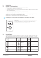
2
Ready
6
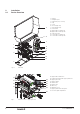
The control panel consists of a graphic display (1) and the navigator pad (2) with five
integrated keys.
The graphic display indicates the current status of the printer and the print job,
indicates faults and shows the printer settings in the menu.
Fig. 5 Control Panel
3.2 Symbol Displays
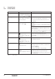
The symbols shown in the following table may appear in the status line of the display, depending on the printer configu-
ration. They enable the current printer status to be seen quickly. For the configuration of the status line the Configu-
ration Manual.
Symbol Description Symbol Description Symbol Description
Clock
Ethernet link status
User memory in the clock
circuit
Date sheet
Temperature of the
printhead
Used memory
Date/time digital
PPP funds
Input buffer
Ribbon supply
Debug window for abc
programs
Access to memory card
Wi-Fi signal strength
Control of the lower
display line is handed
over to an abc program
Printer is receiving data
Table 1 Symbol displays
3 Control Panel