
Brochure/Catalogue


for EMR
for SSR
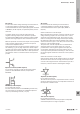
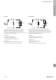
Clearance and creepage
distances
Clearance and creepage distances are critical factors which inuence the
insulation capability of electrical components. The creepage distance denotes
the minimum clearance that two live parts along a surface must have in order to
prohibit a ow of current across the insulating material at the specied operating
voltage.
In addition to the operating voltage, the choice of insulating material (material
group) and the protective measures to counteract pollution (pollution severity)
affect the creepage distance. The clearance distance denotes the minimum
direct clearance (through the air) that two live parts must have to one another in
order to prohibit a charge passing through the air (an arc). The expected surge
voltage (rated impulse voltage) forms the basis for calculating the distances. The
surge protection category and pollution severity are further factors that inuence
dimensional design considerations.
Clearance distance
Creepage distance
Housing contours
Live, current-carrying parts
x x
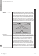
Coil resistance Ohmic resistance (direct current resistance) of a relay coil measured at room
temperature (approx. 23 °C) and coil temperature equal to room temperature.
For AC coils, only the ohmic resistance is specied in the data sheet. The
impedance, which can be calculated from the inductive resistance (reactance)
and the ohmic resistance, only occurs during operation of AC coils and is
considerably greater than the specied ohmic resistance. Therefore, the
information in the data sheets for AC coils is not suitable for calculating the rated
current of the coil.
The coil resistance is heavily dependent on the coil temperature, which is
inuenced by parameters such as the ambient temperature, the rated control
voltage and the duty cycle. Therefore, the values in the application may differ
from the data sheet specications.
The coil resistance is only specied for relays and relay modules that have no
other electronic components upstream from the coil. These types of inputs with
upstream circuitry do not allow for reliable resistance data in the data sheet. For
this reason, no resistance is specied in the data sheet for these inputs or for
solid-state relays.
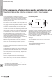
x
EMR = Electromechanical relay
SSR = Solid-state relay
Glossary: Relay modules and Solid-state relays
W
Technical appendix/Glossary
W.16 2737920000