
Brochure/Catalogue


for EMR
for SSR
S
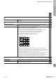
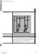
Schmitt trigger Strictly speaking, switching voltages for digital control follow an analogue pattern
(no changeover from 0 to 1 between maximum and minimum voltages).
This can lead to inaccuracies in switching results, above all when signals
are being transmitted rapidly. In this case, the Schmitt trigger functions as a
threshold switch. If the threshold voltage set in the Schmitt Trigger is exceeded,
the output assumes the maximum possible output voltage (logic 1). Otherwise it
is the minimum possible output voltage (logic 0). The Schmitt trigger is normally
designed with a hysteresis. The threshold voltage set for activating is higher than
that for deactivating. That prevents small irregularities from triggering a switching
operation.
x
Self-heating The heating up of an operational component based on the power loss from the
relay coil and the switching contacts.
x
Self-heating, power loss The heating up of a relay module or solid-state relay during operation due to the
power consumption of the input and the power loss from the switching contacts.
The standard DIN EN 61439 “Low-voltage switchgear and controlgear
assemblies - Part 1: General rules“ requires that the heating up of a switching
combination be determined for planners, panel builders and installers. The power
loss of all installed equipment must be taken into account.
However, this presupposes that the respective manufacturers of the equipment
make the corresponding values available. In practice, determining the actual
power loss for certain equipment is difcult and only possible with a lot of effort.
This also includes electromechanical relays and relay modules. We would like to
provide you with a simple recommendation to help calculate these power loss
values for Weidmüller relay modules and solid-state relays.
x x
Self-heating, power loss Power loss in electromechanical relays:
The power loss of a relay module can be calculated by adding the input power
specied in the data sheet to the output power loss. If you want to determine the
real power loss for the output, this depends on a number of parameters such as
switching current, switching frequency, ambient temperature, arcing time, etc.
Performing the calculation using all these values would be almost impossible,
because many of these parameters are not known. Therefore, we recommend
calculating the power loss at the output using a highly simplied formula of
contact resistance and switching current: P = I² x R
The contact resistance is dynamic during the service life, and increases due
to wear, e.g. contact erosion towards the end of the service life. Weidmüller
recommends using 50 mOhm (0.05 Ohm) as the contact resistance for
calculating the output power loss of a relay module. It is not recommended
to measure the contact resistance with a multimeter, because this can give
completely incorrect values. For the maximum power loss, simply insert the
continuous current from the data sheet into the formula.
To calculate a value that is closer to the real power loss, it is recommended to
insert the actual current switched in the application into the formula.
These formulas calculate the power loss for 100% duty cycle If you now want to
determine the value more accurately, the power loss should be multiplied by the
duty cycle (in per cent). With a duty cycle of 50%, the power loss would be halved.
x
EMR = Electromechanical relay
SSR = Solid-state relay
W
Technical appendix/Glossary
W.352737920000
Glossary: Relay modules and Solid-state relays