
Brochure/Catalogue


for EMR
for SSR
Self-heating, power loss Power dissipation in solid-state relays:
The power loss calculation in solid-state relays behaves in almost the same
way as that of electromechanical relays. Here, however, the maximum voltage
drop specied in the data sheet is used instead of the contact resistance. This
voltage drop is essentially dependent on the switched current. At low switching
currents, the voltage drop is low, but it is recommended to use the maximum
voltage drop from the data sheet. The highly simplied formula is then as follows:
P = Uvoltage drop x I
For the maximum power loss, simply enter the continuous current from the
data sheet into the formula. In order to calculate a value that is closer to the
real power loss, it is recommended to insert the actual current switched in the
application into the formula
These formulas calculate the power loss for 100% duty cycle If you now want
to determine the value more accurately, the power loss should be multiplied by
the duty cycle (in per cent). With a duty cycle of 50%, the power loss would be
halved.
x
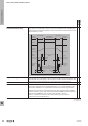
Series-circuit connection of
relay contacts
The serial connection of 2 or more NO contacts of a relay causes the contact
opening to increase on switch-off. Arcs which occur from DC loads are cleared
more quickly which results in reduced burn-off on the contact. This increases
the electrical endurance or the possible switching current or switching voltage.
The possible switching current or the possible switching voltage is shown with
dashed lines in the DC load limit curves diagrams, if specied. Information about
the electrical endurance should not be derived from these curves!
x
Setting tolerance Difference between the measured value of the delay period and the set value on
the time relay.
The specication refers to the full scale value.
The setting tolerance is measured directly at the relay contacts, i.e. a time is set
using the scale on the device and then measured.
The input signal (start of time measurement) is either the power supply or the
control contact, depending on the denition of the function.
The time measurement is ended by switching the output contact.
x x
Short-circuit-proof Switching off the output stage of some solid-state relays whose output was
developed to be short-circuit proof in order to protect the output circuit from
damage in the event of a short circuit.
Solid-state relays without a special design in the output are not short-circuit
proof and must be protected with a special fuse for device protection. A short-
circuit-proof output does not release the user from the obligation to install line
protection to protect the installation.
x
SIL Safety Integrity Level. To reduce risk, the components must comply with the
requirements of IEC 61508. This standard provides general requirements
for avoiding and minimising device and equipment outages. It stipulates
organisation and technical requirements concerning device design and
operation. Four safety levels are distinguished for systems and risk-reducing
measures, ranging from SIL1 for low risk to SIL4 for very high risk. Measures
taken to reduce risk must be more reliable when the classied risk level is higher.
x x
Solid state contactor, Power
Solid-State Relay (PSSR)
A solid-state relay that can switch a high level of power, which is why they are
called semiconductor contactors or PSSR (Power Solid-State Relays).
They are considerably larger than conventional solid-state relays and often have a
heat sink, which is needed in order to remove the power loss in the output.
x
EMR = Electromechanical relay
SSR = Solid-state relay
W
Technical appendix/Glossary
W.36 2737920000
Glossary: Relay modules and Solid-state relays