Controllers u-control Manual (Original) Letʼs connect.
Content 1 1.1 1.2 1.3 About this documentation Symbols and notes Complete documentation Hardware versions described 3 3 3 4 2 2.1 2.2 2.3 2.4 Safety General safety notice Intended use Use in a potentially explosive atmosphere Legal notice 5 5 6 6 7 3 3.1 3.2 3.3 3.4 3.5 3.6 3.7 3.8 System overview General description of the controller General technical data Connectable u-remote I/O modules Connector PG 1.5 mm Mechanical fixing elements Type plate Battery Memory card 9 11 12 13 13 13 14 14 14 4 4.
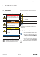
1 About this documentation | Symbols and notes 1 About this documentation 1.1 Symbols and notes The situation-dependent safety notices may contain the following warning symbols: The safety notices in this documentation are designed according to the severity of the danger.
1.3 Hardware versions described The present manual describes the following hardware versions of the controllers: Order No. Controller Hardware version 1334990000 UC20-WL2000-IOT 01.22.00 1334950000 2674520000 2674620000 4 UC20-WL2000-AC UC20-SL2000-EC UC20-SL2000-EC-CAN 01.22.00 01.22.00 01.22.00 Manual u-control 2604080000/03/08.
2 Safety | General safety notice 2 Safety This section includes general safety instructions for handling the u-control system. Specific warning notices for specific tasks and situations are given at the appropriate places in the documentation. Failure to observe the safety and warning notices can result in damage to persons and material. –– When using I/O modules modules, please also observe the Remote-I/O-System u-remote Manual.
2 Safety | Intended use 2.2 Intended use The products of the UC20 series are intended for use in industrial automation. A u-control station comprising a controller and connected u-remote I/O modules is intended for the control of systems or sub-systems. The UC20-WL2000 controllers are configured and programmed using the integrated web application u-create web. The UC20-SL2000 controllers are configured and programmed using the separate engineering tool u-create studio.
2 Safety | Legal notice 2.4 Legal notice The u-control series products are CE-compliant in accordance with Directive 2014/30/EU (EMC Directive) and Directive 2014/35/EU (Low Voltage Directive). They also meet the requirements of the ATEX Directive 2014/34/EU unless otherwise noted. The results of the measurements according to CISPR 16-2-3 should also be suitable to demonstrate the compliance of the u-control devices to the limits for radiated emissions as defined by CFR 47 Part 15, Subpart B, §15.
Manual u-control 2604080000/03/08.
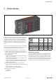
3 System overview 3 System overview Example arrangement of a u-control station The products of the u-control series are programmable logic controllers. The UC20-WL2000 controllers are configured, parameterised and programmed using the integrated engineering tool u-create web via a web browser. The UC20SL2000 controllers are configured, parameterised and programmed using the separate engineering tool u-create studio. Up to 64 active u-remote I/O modules can be connected to a controller.
3 System overview Power supply concept The u-control controllers and the u-remote modules use three internal current paths as described in following chapter 4. Input and output paths are supplied seperately, therefore a custom-fit refreshing by power-feed modules is easyly feasible. The figure shows the general supply concept. For detailed description and calculation of the current demand please regard sections 4.6 and 4.7.
3 System overview | General description of the controller 3.1 General description of the controller 1 4 7 5 8 6 2 9 13 14 15 16 10 3 17 11 18 12 13 Controller (example: UC20-SL2000-EC-CAN) 1 2 3 4 5 6 Release lever for the DIN rail fixing Data line connection (RJ45) CAN interface (only UC20-SL2000-EC-CAN) Seats for module markers Type designation Swivel marker for labelling modules and channels (optional) 2604080000/03/08.
3 System overview | General technical data 3.2 General technical data Type of connection "PUSH IN" Configuration interface Dimensions USB 2.0 Protection class (IEC 60529) Flammability rating UL 94 Temperature data Humidity Air pressure Vibration resistance Shock resistance Potential isolation Approvals and standards solid, fine-wired Wire cross-section 0.14 ... 1.5 mm2 (AWG 16 – 26) Height Width 120.0 mm / 4.72" (with release lever: 128.0 mm / 5.04") 52.0 mm / 2.05" Depth 76.0 mm / 2.
3 System overview | Connectable u-remote I/O modules 3.3 Connectable u-remote I/O modules The release notes concerning the controllers describe which u-remote modules at which firmware version are supported. The release notes are available to download from the Weidmüller website. 3.5 Mechanical fixing elements The station is fixed in the installation position by an end bracket at either side. The last I/O module is protected against dust by a cover plate.
3 System overview | Type plate 3.6 Type plate 3.7 Each controller features a type plate, which includes identification information and the key technical specifications. In addition, a QR code allows for direct online access to the associated documentation. The software for reading the QR code must support inverted QR codes. A breakdown of the serial numbers can be found in the table provided in the annex. Battery The controller can be equipped with a battery (for specification see technical data).
4 Configuration | Order and arrangement of the modules Configuration 4.1 Order and arrangement of the modules 4.2 The u-control station is designed to be installed on a DIN rail (35 × 7.5 mm or 35 x 15 mm) made from steel or galvanised steel according to EN 60715. Orientation of the station The u-control station is usually installed on a horizontally positioned DIN rail. –– A u-remote station may be built up to a maximum length of 1 m. Therefore at most 82 modules (including max.
4 Configuration | Installation distances 4.3 Installation distances In order to be able to carry out the installation and subsequent maintenance work and to ensure sufficient ventilation, the u-control station must be installed while observing the following minimum distances (see the following figures). ATTENTION Depending on how the station shielding is implemented, the specified distances may have to be made larger, where necessary.
4 Configuration | Use in a potentially explosive atmosphere 4.4 Use in a potentially explosive atmosphere Please regard the safety notes in section 2.3. You will find the module specific data needed for calculation in the document "WI13ATEX0002_Power_Calc.pdf" which you can download from the Weidmüller website. If the u-remote station is used in a potentially explosive atmosphere rated as Zone 2, the housing must meet the requirements of explosion protection type Ex n or Ex e and protection class IP54.
4 Configuration | Current demand and power supply 4.6 Current demand and power supply ATTENTION The u-control controllers use three internal current paths: The ISYS system current path supplies the communication part of the I/O modules; it is fed from the controller input supply and cannot be interrupted by any module. The maximum current-carrying capacity of ISYS allows a u-control station to be expanded with a maximum of 64 active modules without having to refresh the power.
4 Configuration | Example calculation for the power supply 4.7 Example calculation for the power supply The power supply must be calculated individually for each station installation. Therefore the simultaneity factor g and the current demand of each module, as well as the devices to be connected must be established (see the example calculation table). In the example station, a UC20-WL2000-AC controller is configured with four UR20-4DI-P modules and eight UR20-8DO-P modules.
4 Configuration | Example calculation for the power supply Example calculation for the current demand (all current values in A) Module no. Product ISYS IIN IOUT IS IL Simultaneity factor g Cumulative current demand of the input current path Cumulative current demand of the controller output power path UC20-WL2000-AC 0.116 0.116 0 1 UR20-4DI-P 0.008 0.012 0.06 1 0.196 0 2 UR20-4DI-P 0.008 0.012 0.06 1 0.276 0 3 UR20-4DI-P 0.008 0.012 0.12 1 0.416 0 4 UR20-4DI-P 0.
4 Configuration | Calculation of power loss 4.8 Calculation of power loss 4.
Manual u-control 2604080000/03/08.
5 Detail description of controllers | UC20-WL2000-AC 5 Detail description of controllers 5.1 UC20-WL2000-AC Status indicators Up to 64 active u-remote modules can be connected via the u-remote system bus to the UC20-WL2000-AC controller. The controller has two Ethernet connections for integration into the existing network architecture or HMI connections. X1 AC PWR SF The integrated engineering tool u-create web can be launched via the USB service interface or over Ethernet.
5 Detail description of controllers | UC20-WL2000-AC AC Controller power supply LED Green: supply voltage > 18 V Red: at least one current path < 18 V PWR SF BF TD+ TD– RD+ RD– 1 2 3 6 TD+ TD– RD+ RD– 1 2 3 6 AC X1 MT RUN/STOP L/A X1 L/A X2 X2 24 V DC IN 24 V DC IN GND IN GND IN 3.1 Green: input current path supply voltage > 18 V DC 3.2 Red: input current path supply voltage < 18 V DC 24 V DC OUT 24 V DC OUT GND OUT GND OUT 3.4 Red: Internal fuse defective Service X3 4.
5 Detail description of controllers | UC20-WL2000-AC USB 8x µC Internal from the control card DC Battery System bus System bus USYS USYS UIN UIN UOUT UOUT DC 24 V/5 A Input SD card System bus UIN RTC UOUT RJ45 RJ45 24 V/5 A Output UC20-WL2000-AC Block diagram UC20-WL2000-AC 2604080000/03/08.
5 Detail description of controllers | UC20-WL2000-AC Technical data UC20-WL2000-AC (Order No. 1334950000) System data Connection 2 x RJ-45 Number of modules max. 64 active Configuration interface Micro USB 2.0 Processor Dual Core ARM A9, 624 MHz Memory 512 MB RAM, 4 GB flash Retain memory 128 KB NV-RAM Memory card (not included) microSD (max.
5 Detail description of controllers | UC20-WL2000-IOT 5.2 UC20-WL2000-IOT Status indicators Up to 64 active u-remote modules can be connected via the u-remote system bus to the UC20-WL2000-IOT controller. The controller has two Ethernet connections for integration into the existing network architecture or HMI connections. X1 IOT PWR SF The integrated engineering tool u-create web can be launched via the USB service interface or over Ethernet.
5 Detail description of controllers | UC20-WL2000-IOT IOT Controller power supply LED Green: supply voltage > 18 V Red: at least one current path < 18 V PWR SF BF TD+ TD– RD+ RD– 1 2 3 6 TD+ TD– RD+ RD– 1 2 3 6 IOT X1 MT RUN/STOP L/A X1 L/A X2 X2 24 V DC IN 24 V DC IN GND IN GND IN 3.1 Green: input current path supply voltage > 18 V DC 3.2 Red: input current path supply voltage < 18 V DC 24 V DC OUT 24 V DC OUT GND OUT GND OUT 3.4 Red: Internal fuse defective Service X3 4.
5 Detail description of controllers | UC20-WL2000-IOT USB 8x µC Internal from the control card DC Battery System bus System bus USYS USYS UIN UIN UOUT UOUT DC 24 V/5 A Input SD card System bus UIN RTC UOUT RJ45 RJ45 24 V/5 A Output UC20-WL2000-AC Block diagram UC20-WL2000-IOT 2604080000/03/08.
5 Detail description of controllers | UC20-WL2000-IOT Technical data UC20-WL2000-IOT (Order No. 1334990000) System data Connection 2 x RJ-45 Number of modules max. 64 active Configuration interface Micro USB 2.0 Processor Dual Core ARM A9, 624 MHz Memory 512 MB RAM, 4 GB flash Retain memory 128 KB NV-RAM Memory card (not included) microSD (max.
5 Detail description of controllers | UC20-SL2000-EC 5.3 UC20-SL2000-EC Status indicators Up to 64 active u-remote modules can be connected via the u-remote system bus to the UC20-SL2000-EC controller. The controller has two Ethernet connections for integration into the existing network architecture or HMI connections. X1 AC PWR SF The controller can be configured as a EtherCAT master.
5 Detail description of controllers | UC20-SL2000-EC AC Controller power supply LED Green: supply voltage > 18 V Red: at least one current path < 18 V PWR SF BF TD+ TD– RD+ RD– 1 2 3 6 TD+ TD– RD+ RD– 1 2 3 6 AC X1 MT RUN/STOP L/A X1 L/A X2 X2 24 V DC IN 24 V DC IN GND IN GND IN 3.1 Green: input current path supply voltage > 18 V DC 3.2 Red: input current path supply voltage < 18 V DC 24 V DC OUT 24 V DC OUT GND OUT GND OUT 3.4 Red: Internal fuse defective Service X3 4.
5 Detail description of controllers | UC20-SL2000-EC USB 8x µC Internal from the control card DC Battery System bus System bus USYS USYS UIN UIN UOUT UOUT DC 24 V/5 A Input SD card System bus UIN RTC UOUT RJ45 RJ45 24 V/5 A Output UC20-SL2000-EC Block diagram UC20-SL2000-EC 2604080000/03/08.
5 Detail description of controllers | UC20-SL2000-EC Technical data UC20-SL2000-EC (Order No. 2674520000)) System data Connection 2 x RJ-45 Number of modules max. 64 active Configuration interface Micro USB 2.0 Processor Dual Core ARM A9, 624 MHz Memory 512 MB RAM, 4 GB flash Retain memory 128 KB NV-RAM Memory card (not included) microSD (max.
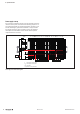
5 Detail description of controllers | UC20-SL2000-EC-CAN 5.4 UC20-SL2000-EC-CAN Status indicators Up to 64 active u-remote modules can be connected via the u-remote system bus to the UC20-SL2000-EC-CAN controller. The controller has two Ethernet connections for integration into the existing network architecture or HMI connections. SL-EC-CAN X1 PWR SF BF The controller has a CAN interface.
5 Detail description of controllers | UC20-SL2000-EC-CAN X1 TD+1 TD– 2 RD+3 RD–6 PWR SF BF MT RUN X2 TD+1 TD– 2 RD+3 RD–6 L/A X1 L/A X2 3.1 Green: input current path supply voltage > 18 V DC 24V DC IN 24V DC IN GND IN GND IN 3.2 Red: input current path supply voltage < 18 V DC X4 GND CAN L CAN H SL-EC-CAN Controller power supply LED Green: supply voltage > 18 V Red: at least one current path < 18 V 3.4 Red: Internal fuse defective 4.1 Green: Output current path supply voltage > 18 V DC 4.
5 Detail description of controllers | UC20-SL2000-EC-CAN USB 8x µC Internal from the control card DC Battery RTC System bus System bus USYS USYS UIN UIN UOUT UOUT DC 24 V/5 A Input SD card System bus UIN RJ45 UOUT RJ45 CAN 24 V/5 A Output UC20-SL2000-EC-CAN Block diagram UC20-SL2000-EC-CAN 2604080000/03/08.
5 Detail description of controllers | UC20-SL2000-EC-CAN Technical data UC20-SL2000-EC (Order No. 2674520000)) System data Connection 2 x RJ-45, 1 x CAN interface Number of modules max. 64 active Configuration interface Micro USB 2.0 Processor Dual Core ARM A9, 624 MHz Memory 512 MB RAM, 4 GB flash Retain memory 128 KB NV-RAM Memory card (not included) microSD (max.
6 Installation | Preparations for assembly 6 Installation Stripping lengths WARNING Explosion risk! During assembly work, sparks can form and surfaces may become excessively hot. ▶▶ Before assembly, make sure that there is not a potentially explosive atmosphere! ▶▶ For applications in potentially explosive atmospheres, observe the installation and construction requirements of EN 6007915 and/or country-specific regulations.
6 Installation | Preparations for assembly In the case of vertical mounting, the controller must always be arranged as the first module at the bottom and secured with a reinforced end bracket for vertical mounting (Order no. 1805610000). Use in a potentially explosive atmosphere Please regard the safety notes in section 2.3.
6 Installation | Preparations for assembly For vertical installation interchange height and width. When calculating the width, 4.5 mm for the must be added for the end bracket MEW 35/1 (Order No. 1805610000). 20 mm 0.97" Installation sequence 35 mm 1.38" 40 mm 1.57" If the station has already been configured, please proceed to the corresponding installation drawing.
6 Installation | Assembling the u-control station 6.2 Assembling the u-control station WARNING Explosion risk! ▶▶ Prior to starting work, make sure that there is not a potentially explosive atmosphere! WARNING Dangerous contact voltage! ▶▶ All work on the u-control station must be carried out with the power supply disconnected. ▶▶ Make sure that the place of installation (switch cabinet etc.
6 Installation | Assembling the u-control station ▶▶ Place the controller (module side to the right) on the DIN rail so that it audibly clicks into place. X1 X X1 X Sliding the module into position Attaching the controller to the DIN rail ▶▶ Slide the controller to the left until it completely connects with the end bracket. At the same time, press the controller as close as possible to the DIN rail so that the controller is not tilted. ▶▶ Attach all of the other modules as described above.
6 Installation | Wiring 6.3 Wiring Wiring of modules with connectors PG 1.5 mm Only copper wires with a cross section between 0.14 mm² and 1.5 mm² (AWG 16 – 26) may be connected. WARNING Explosion risk! ▶▶ Before assembly, make sure that there is not a potentially explosive atmosphere! ▶▶ For applications in potentially explosive atmospheres, observe the installation and construction requirements of EN 6007915 and/or country-specific regulations.
6 Installation | Inserting the battery 6.4 Inserting the battery + WARNUNG Explosion risk! ▶▶ Do not use the controller with a battery in a potentially explosive atmosphere. WARNING Battery may explode if mistreated! Use of a wrong battery type may cause fire or explosion! ▶▶ Do not recharge, disassemble or dispose of in fire. ▶▶ Use only batteries of the specified type (see technical data). Inserting the battery ▶▶ Close the connector frame.
6 Installation | Inserting the SD card 6.5 Inserting the SD card 6.6 ▶▶ Unlock the connector frame and open it as far as possible (at least to an angle of 90°). Insulation test Insulation tests on the u-control station have to be done according to the national regulations, in any case necessarily before each commissioning.
7 Earthing and shielding 7 Earthing and shielding The terms “earths” and “shields” are classified according to their relation to human safety or system safety. An earth is installed primarily to protect human life, and for this reason it is referred to as the protective earth (PE) conductor. A shield, on the other hand, serves to ensure the trouble-free operation of an electrotechnical system as well as electromagnetic compatibility.
7 Earthing and shielding | Earthing of shielded cables 7.1 Earthing of shielded cables Electrical and electronic systems must be designed such that they are largely safeguarded against electrical interference, thus enabling them to operate securely even in the case of transient interference voltages. Electrical interference can be introduced into electric circuits in a variety of ways. The most frequent causes are due to inductive interference.
7 Earthing and shielding | Earthing of shielded cables In practice, the shield is still often twisted and connected to a terminal point. There is very high attenuation (voltage drop) on these connections, especially for high-frequency interference. Therefore, this type of shielding should not be used, even for short cable lengths. The shielding of the cable is practically negated and can, at best, be helpful for low-frequency interference.
7 Earthing and shielding | Earthing of shielded cables Effective shielding It is important that the shielding is not positioned on the earth of the connected component, but on the protective earth. In the case of components that are installed in a metal housing, the shielding must be positioned to this housing. If no earthed housing is available, the shielding is positioned on a separate earth. When installing ground connections on shielding, it is generally also important that no earth loops are created.
7 Earthing and shielding | Earthing of shielded cables Ø 3-37 mm KLBÜ CO KLBÜ CPF Ø 3-32 mm KLBÜ SC C-Profil Mounting accessories Ø 3-32 mm TS35 KLBÜ KLBÜ Z/1 Ø 4-6 mm Ø 2-32 mm Carrier systems TS35 Overview of the product line for shielding connections Please refer to our Modular Terminals Catalogue for more information. Order No.: 1282250000 2604080000/03/08.
7 Earthing and shielding | Potential ratios 7.
7 Earthing and shielding | Potential ratios DI/AI FE FE DO/AO FE PF-O FE DO/AO FE PF-I FE DI/AI FE DIN rail PE earthing concept: The spring contacts underneath the components snap into the DIN rail to make a connection. 2604080000/03/08.
7 Earthing and shielding | Electromagnetic compatibility (EMC) 7.3 Electromagnetic compatibility (EMC) PE connection u-control products and u-remote products completely meet EMC requirements. EMC planning, however, is necessary prior to installation. The connection from earth to the PE (protective earth) connection must be done centrally.
7 Earthing and shielding | Electromagnetic compatibility (EMC) 1 Earthing strips Earthing strips must be used for connecting inactive metal parts if it is not possible to connect two large pieces of metal. Use short earthing strips with large surfaces. Cabinet design according to EMC guideline: 2 Clamping bracket for signal cables If shielded signal cables are used, the shield must be attached to the clamping bracket (KLBÜ series) on the busbar over a large surface.
7 Earthing and shielding | Shielding of cables 7.4 Shielding of cables ATTENTION To prevent the coupling of interference voltages and the decoupling of interference fields in cables, only shielded cables made from well-conducting material (copper or aluminium) with braided shielding and a coverage of at least 80 % should be used in the design of a cable shield.
7 Earthing and shielding | Shielding of cables Equipotential bonding 2604080000/03/08.
Manual u-control 2604080000/03/08.
8 Commissioning using u-create web | Requirements 8 Commissioning using u-create web Web browser WARNING Explosion risk! ▶▶ Before starting any work, make sure that there is not a potentially explosive atmosphere! WARNING! Manipulation of the control unit! During commissioning, the system may be manipulated to such an extent that can result in risks to life and material damage.
8 Commissioning using u-create web | Accessing u-create online help 8.3 Accessing u-create online help The built-in online help describes how to operate u-create. Login window (Example: Google Chrome) Your login details are requested. The following login data are then requested: user name: admin password: Detmold ▶▶ Enter the username and password and confirm. The u-create web starting page is displayed. Accessing the online help ▶▶ On the starting page, click Help.
8 Commissioning using u-create web | Resetting the controller to default settings The connection to u-create is interrupted, the controller restarts and the page SWUpdate is displayed in the browser. 8.5 Resetting the controller to default settings The following data are reset: –– The current runtime application is removed. –– The controller is restarted. –– The IP address is reset to the standard IP address. –– The working copy is deleted. ▶▶ On the starting page, click Settings.
Manual u-control 2604080000/03/08.
9 Commissioning using u-create studio | Requirements 9 Commissioning using u-create studio 9.2 WARNING Explosion risk! ▶▶ Before starting any work, make sure that there is not a potentially explosive atmosphere! The UC20-SL2000 controllers do not have any firmware installed on delivery except for the hardware-related software. You must first create the firmware in u-create studio as a target and load it onto the controller via SD card.
9 Commissioning using u-create studio | Starting „DevAdmin“ ▶▶ Open a web browser. ▶▶ In the address bar, enter the IP address of the controller. –– Ethernet access: 192.168.101.100 DevAdmin is started. You will be asked to enter your login data. The following login data is valid on delivery: Username: Administrator Password: tobechanged Diagnostic view Login data (on delivery) ▶▶ Enter the username and password and confirm the entry. The Diagnostic view of DevAdmin is displayed.
10 Replacing components | Removing/replacing the plug-in unit 10 Replacing components 10.1 Removing/replacing the plug-in unit ▶▶Swivel the plug-in unit with the cabling towards the front by 90°. WARNING Explosion risk! ▶▶ Prior to starting work, make sure that there is not a potentially explosive atmosphere! WARNING The plug-in unit can only be removed in this 90° position! ▶▶ Remove the plug-in unit by pulling it out in a straight, downward motion.
10 Replacing components | Removing/replacing connectors 10.
10 Replacing components | Removing/replacing cables 10.3 Removing/replacing cables ▶▶ Using a 3-mm screwdriver, push in the pusher adjacent to the cable to be removed and pull the wire out.
10 Replacing components | Replacing the battery 10.
10 Replacing components | Replacing the SD card 10.
Manual u-control 2604080000/03/08.
11 Disassembly and disposal | Disassembling the u-remote station 11 Disassembly and disposal 11.1 Disassembling the u-remote station 11.2 Disposing of the u-control station WARNING ATTENTION Explosion risk! ▶▶ Prior to starting work, make sure that there is not a potentially explosive atmosphere! Products in the u-remote series are subject to WEEE (EU Directive 2012/19/EU), which regulates the collection and recycling of electrical and electronic equipment.
Manual u-control 2604080000/03/08.
12 LED indicators and troubleshooting 12 LED indicators and troubleshooting In the event of a malfunction occurring on a u-control product, carry out the following recommended measures. If the malfunction cannot be fixed, please send the affected product to Weidmüller. You can find all Weidmüller addresses and your local contact on the Internet at www.weidmueller.com.
12 LED indicators and troubleshooting Controller/indicator LED Status Recommended action Power LED PWR green: supply voltage present, firmware is running – System failure SF red: serious system failure Bus failure BF green: communication with modules OK Switch supply voltage off and on again and deploy application again UC20-WL2000-IOT Check whether modules are mounted correctly green flashing twice: operating system is running – off: no application deployed – green: application is d
12 LED indicators and troubleshooting Controller/indicator LED Status Recommended action green: supply voltage present, bootloader/firmware is running – Check whether modules are mounted correctly Check if the configured station setup matches the actual setup Read off the diagnostic message from the engineering tool and determine which further actions to take UC20-SL2000-EC , UC20-SL2000-EC-CAN Power LED PWR System failure SF Bus failure BF red: field bus failure Maintenance MT yellow: com
Manual u-control 2604080000/03/08.
13 Accessories and replacement parts | Accessories 13 Accessories and replacement parts 13.1 Accessories Order No. Designation Purpose 9008320000 Screwdriver SDS 0.5X3.0X80 Assembling/disassembling an end bracket 1323700000 PM 2.7/2.6 MC SDR marker 1323710000 PM 2.7/2.6 MC NE WS marker Connection marker for a pusher, with custom printing to customer specifications 1341610000 DEK 5/8-11.5 MC SDR marker Module marker with custom printing to customer specifications 1341630000 DEK 5/8-11.
13 Accessories and replacement parts | Replacement parts 13.2 Replacement parts 78 Controller Order No. Replacement part Order No. UC20-WL2000-AC 1334950000 2425170000 UC20-WL2000-IOT 1334990000 Plug-in unit UR20-PK-1334940000-SP UC20-SL2000-EC 2674520000 2425170000 UC20-SL2000-EC-CAN 2674620000 Plug-in unit UR20-PK-1334940000-SP PCB plug-in connector for CAN interface B2CF 3.
ANNEX Examples of module position coding A-2 Breakdown of Serial Numbers A-4 Service A-5 2604080000/03/08.
Examples of module position coding The incorrect insertion of electronic units can be prevented if the base modules are given coding elements KOSM BHZ5.00 (Order No.1483050000) Three coding sockets each with four possible positions can be plugged into every base module. This results in a maximum of 43 or 64 codes. It is practical to use either functionally oriented or slotoriented coding. Example codes are provided for each coding scheme in the following tables.
Slot-oriented coding Slot-oriented coding Coding position Code 01 02 1 0 0 2 0 0 3 0 1 Coding position Station slot Code 1 2 3 Station slot 2 34 2 0 1 34 2 0 2 35 1 33 2 0 0 33 03 0 0 2 3 35 04 0 0 3 4 36 2 0 3 36 05 0 1 0 5 37 2 1 0 37 06 0 1 1 6 38 2 1 1 38 07 0 1 2 7 39 2 1 2 39 08 0 1 3 8 40 2 1 3 40 09 0 2 0 9 41 2 2 0 41 10 0 2 1 10 42 2 2 1 42 11 0 2 2 11 43 2 2 2 43 12 0 2 3 12
Breakdown of Serial Numbers Position 1 Year Code Month 3 Code 4 Day Code Production plant 5 Code 0 1 2 0 2 3 0 3 4 4 0 4 5 5 5 0 5 June 6 6 6 0 6 July 7 7 7 0 7 U August 8 8 8 0 8 A V September 9 9 9 0 9 2022 A W October O 10 A 1 0 2023 A X November N 11 B 1 1 2024 A Y December D 12 C 1 2 2025 A Z 13 D 1 3 2026 B A 14 E 1 4 2027 B B 15 F 1 5 2028 B C 16 G 1 6 2029 B D 17 H 1 7 2030 B E
Service If you have any questions about u-remote, please contact your responsible country representatives. You can find all Weidmüller addresses and your local contact on the internet at: www. weidmueller.com/countries Sales company Representation abroad without representation abroad Let’s connect. MD ME MG MK Moldova BERHORD A & D srl 79/1, str. Milescu Spartaru MD-2075 Chisinau Moldova Tel. +373 (22) 815002 Fax +373 (22) 815007 atiuleanu@berhord.com www.ad.berhord.
Weidmüller – Your Partner in Industrial Connectivity As experienced experts we support our customers and partners around the world with products, solutions and services in the industrial environment of power, signal and data. We are at home in their industries and markets and know the technological challenges of tomorrow. We are therefore continuously developing innovative, sustainable and useful solutions for their individual needs. Together we set standards in Industrial Connectivity.