Remote-I/O-System u-remote Web server manual Letʼs connect.
Content Manufacturer Weidmüller Interface GmbH & Co. KG Klingenbergstraße 26 32758 Detmold, Germany T +49 5231 14-0 F +49 5231 14-292083 www.weidmueller.com 1 1.1 1.2 About this documentation Symbols and notes Complete documentation 3 3 3 2 Safety 4 3 3.1 3.2 Product description and requirements Product description Requirements 5 5 5 4 4.1 4.2 Connecting and starting the web server Installing the web server via USB Starting the web server 6 6 7 5 5.1 5.2 5.3 5.4 5.5 5.6 5.7 5.
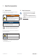
1 About this documentation 1.1 Symbols and notes 1.2 The safety notices in this documentation are designed according to the severity of the danger. WARNING Possible danger to life! Notes with the signal word “Warning” warn you of situations which may result in serious injury or death if you do not follow the instructions given in this manual. Complete documentation – This manual describes how to use the web server application (Version 2.2.0 or higher).
2 Safety This section includes general safety instructions for handling the web server. Specific warning notices for specific tasks and situations are given at the appropriate places in the documentation. Failure to observe the safety and warning notices can result in damage to persons and material. – Please also observe the manual u-remote I/O-System. – When using safe I/O modules, please also observe the manual Modules for functional safety.
3 Product description and requirements 3.1 Product description With the web server, the u-remote station is displayed on a connected PC. This allows you to carry out the following tasks e.g.
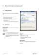
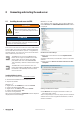
4 Connecting and starting the web server 4.1 Installing the web server via USB WARNING Explosion risk! ▶ Prior to starting work, make sure that there is not a potentially explosive atmosphere! Windows 7® or older ▶ To install the driver manually, open the Device Manager. Under Other devices the USB CDC-RNDIS Network Interface interface is displayed.
Connecting and starting the web server | Starting the web server ▶ Follow the rest of the steps in the installation routine until the successful installation is confirmed. The driver is displayed in the Device Manager under Network adapters. ▶ Close the Device Manager. 4.2 Starting the web server The u-remote station must be completely assembled and supplied with voltage. ▶ Connect the PC to the coupler using a USB cable.
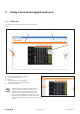
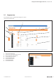
5 Getting to know and arranging the web server 5.1 Station view The station view is displayed on every start up of the web server. 2 3 4 1 5 Station view 1 2 3 4 5 Switch over to the component list (by mouseover) Access to the web server functions Menue bar Detail view of module/channel (by mouseover) Switch over to the component view (by mouse click) Scaling the view up or down The web server only registers modules that can communicate on the system bus.
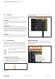
Getting to know and arranging the web server | Component view 5.2 Component view The component view is opened after clicking on a component or the component list.
Getting to know and arranging the web server | Navigation 5.3 Navigation When using a smaller view you can scale up single components by a mouseover. There are several options how to display the station or certain components (coupler or modules): Station view This view shows all components and you can display details via mouseover. You can open the station view with a click on Overview. Component view This view shows a single component (coupler or module) with its information and parameter settings.
Getting to know and arranging the web server | Setting the language Showing or hiding contents ▶ To display the contents of an entry, click on the plus symbol. 5.5 Setting the language The web server starts with the language setting of your browser. If this language is not supported, it starts with the setting English. Three language files for the web server are included in each coupler. On delivery, the languages German, English and Chinese are included.
Getting to know and arranging the web server | Login data and password protection The new language is transferred to the coupler. After a restart of the coupler, you can select the new language in the Language menu. 5.
Getting to know and arranging the web server | Setting up the Ethernet port 5.7 Setting up the Ethernet port Couplers for ethernet based bus systems are equipped with RJ45 sockets. With this, the web server can alternatively be controlled via Ethernet. If you want to use the web server via Ethernet you have to set up the ethernet connection first. ▶ Connect the PC with the coupler (or a switch within the network) using a LAN cable. ▶ Click on the coupler in the station view and then on Parameter.
Getting to know and arranging the web server | HTTPS 5.8 HTTPS Opening the web server via HTTPS With HTTPS, the web server and client communicate encrypted on the transport layer. This ensures the authenticity of the server as well as the integrity and confidentiality of the data transmitted. The following u-remote couplers support HTTPS: Best.-Nr.
Getting to know and arranging the web server | HTTPS Exchanging the TLS/SSL certificate You can replace the u-remote standard certificate with your own certificate. Optionally, you can have your certificate signed by a trusted certificate authority (CA) and also load the CA certificate to the coupler. Only transmit certificates and private keys via trusted connections. We recommend transmitting certificates and private keys via the USB port of the coupler. The web server supports: – Encryption with TLS 1.
Getting to know and arranging the web server | HTTPS Restart the web server The web server is restarted. After the restart, the user-defined certificate is activated. User-defined certificate successfully activated 16 u-remote web server manual 2112220000/06/01.
6 Coupler settings 6.1 ▶ Open the coupler component view. Displaying and changing parameters ▶ Open the coupler component view. ▶ Click Parameter. The parameters are displayed. For parameters that can be edited, you can enter the changes in the entry fields or choose alternative settings from a drop-down list.
Coupler settings | Saving or restoring module parameters in the coupler 6.2 Saving or restoring module parameters in the coupler You can save the parameters of the connected modules in the coupler or restore them to the default values. 6.3 With a reset, you can undo all the changes that have been made since the last time that the web server was started. After a reset, the coupler is restarted. All data which is not protected against power failure is reset. ▶ Click Module parameters.
Coupler settings | Resetting the coupler to factory settings 6.4 Resetting the coupler to factory settings This function allows you to set up the coupler in its original state as at delivery. This includes the reset of the following data: – All coupler parameters – Login data and password protection – I&M data – Modified module parameters that are safed in the coupler During a reset, the coupler is restarted. ▶ Open the coupler component view. ▶ Click Factory settings and then Yes.
7 Module settings ▶ Open the module component view. Displaying and editing module parameters Module component view Here you can: – Display general information about the module – Access and change the module parameters – Display information about certain channels – Access the data sheet of the module (link Ordering data) The module settings are only accessible when force mode is not active. Parameters can only be written when the field bus is not active. 7.1 ▶ Enter the desired modifications.
Module settings | Displaying register settings 7.2 Displaying register settings For modules with registers (e.g. counter modules and PWM modules), the register settings can be displayed in a tool tip. ▶ Open the module component view. ▶ Move the cursor over the value of the register you want to see. Displaying the register settings The registers displayed in bold are set, all others are not set. 7.
8 Configuration and station data 8.1 Saving or loading station parameters When using PROFINET or PROFIBUS you can continue working. ▶ With all other fieldbus protocols you have to restart the coupler. Via the stations parameters function, you can save the current configuration of the u-remote station or load an existing configuration into the coupler. This makes arranging several stations of identical setup very easy.
Configuration and station data | Saving or loading station parameters and channel names Creating a template First you need to create a template file which represents the entire station with all modules and channels. ▶ Click Create template. The file channelnames_template.csv is generated. You can open the file or save it on your computer.
Configuration and station data | Saving or opening a L5X file 8.5 Displaying process data ▶ Click Station data/Process data. Saving or loading a customisation file ▶ To save station parameters and channel names, click Save. You can open the file or save it on your computer. ▶ To load station parameters and channel names, click Load. ▶ Navigate to the desired file on your computer and click Open. Station parameters and channel names are loaded into the coupler and displayed in the web server. 8.
Configuration and station data | Displaying diagnostic data Display of diagnostic data 2112220000/06/01.
9 Web server in force mode 9.1 Activating the force mode WARNING! Manipulation of the control unit! In force mode, the system may be manipulated to such an extent that can result in lifethreatening personal injury and damage to materials. Only use force if you are very familiar with the connected system and know at all times the consequences that your actions will have! If the force mode is activated during an established field bus connection a diagnose alarm is generated.
Web server in force mode | Forcing via the station view 9.2 Forcing via the station view ▶ Click on the channel to be forced. Dependent on the module type there are different options: ▶ To switch an output, click the switch and then Force. Forcing registers Forcing an output ▶ To force counter readings, type in the force values and click Force. ▶ Set or remove the check mark for each register to be forced and click Apply changes. ▶ Click Force. The changes are transferred to the coupler. 9.
Web server in force mode | Deactivating the force mode Detail view of the station in force mode All active modules are displayed in the detail view. The switchable channels are provided with a switch. Display with filter set ▶ To see all channel details, click Show all. ▶ To see only the first value of each channel, click Hide all. Resetting filters Filtering the module view If you only want to see the modules that you would like to force, use the filter function. ▶ Click Filter.
10 Updating the firmware ▶ Download the latest firmware for each component you want to update from the Weidmüller website. Firmware files for fieldbus couplers have the extension .bsc. For PROFINET couplers, for instance, the file might be named FBC-PN-IRT-00XX.bsc. The compatibility is checked during uploading the coupler firmware. Thus it is not possible to load an incompatible coupler firmware. Firmware files for modules have the extension .bsm.
Updating the firmware | Deactivating the force mode The firmware is updated. Once the data has been transferred, you are asked to restart the coupler. ▶ Click Reset. ▶ Wait until the coupler has been restarted and the station view is displayed in the web server. In case the web server does not restart, please act as follows: ▶ Clear the temporary browser data (cache). Deleting the browser protocol is not sufficient. ▶ Start the web server again. 30 u-remote web server manual 2112220000/06/01.
11 Help and FAQ ▶ Click Details.... The Network Connection Details window is opened. 11.1 The web server cannot be loaded – Are coupler and PC properly connected via an USB cable? – Is the IP address for the USB port set correctly (see section 11.2) – Clear the temporary browser data (empty cache, deleting the browser protocol is not sufficient) and reload the web server. – If you call up the web server via HTTP, try calling up the web server via HTTPS.
Help and FAQ | Documentation 11.4 Documentation ▶ Click Help. Help dialogue ▶ To open the manuals for the u-remote station and the webserver, click on the link. A connection to the Weidmüller website is established in a new browser window. 32 u-remote web server manual 2112220000/06/01.
Weidmüller – Your Partner in Industrial Connectivity As experienced experts we support our customers and partners around the world with products, solutions and services in the industrial environment of power, signal and data. We are at home in their industries and markets and know the technological challenges of tomorrow. We are therefore continuously developing innovative, sustainable and useful solutions for their individual needs. Together we set standards in Industrial Connectivity.