
User Documentation


4 Module descriptions | Digital input and output modules IP67, PROFIBUS, 30mm, plastic housing
72484950000/00/03.2016 Manual UR67-PROIFBUS
Digital input module UR67-PB-12-8DI-8-30K (Order No. 2426360000)
Digital input/output module UR67-PB-12-8DIO-8-30K (Order No. 2426330000)
The digital I/O modules IP67 are designed for the decentral-
ised control within a PROFIBUS network. Each module pro-
vides eight ports (M8) for signal lines as well as eldbus con-
nection ports (M12, B-coded) and power supply ports (M12).
UR67-PB-12-8DI-8-30K
I/O module with 8 digital inputs (p-switching)
UR67-PB-12-8DIO-8-30K
I/O module with 8 digital channels (p-switching), congur-
able as inputs or outputs
ATTENTION
The product can be destroyed!
Using a power supply with current regulation or a wrong
fuse will disable the reverse polaritiy protection.
▶ Protect the actuator supply with a overcurrent protect-
tion (6A, mT) that will release at least 10 – 100ms
after a short circuit.
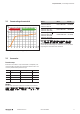
Diagnosis and status LED
LED Indicator Meaning
BF red Bus error
DIA red Collective indicator for peripheral errors
1 ... 8
yellow Channel status
red Peripheral error
U
S
green Sensor/system supply
U
L
green Actuator supply
LED indicators, error messages see chapter9
BF
1
2
3
4
5
6
7
DIA
8
U
S
L
U
UR67-PB-12-8DIO-8-30K
x10
x1
IN
OUT
BUS
AUX IN
5
0
1
2
3
4
9
8
7
6
5
0
1
2
3
4
9
8
7
6
2
2
1
6
5
7
4
9
3
8
2
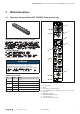
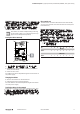
Product details UR67-PB-12-8DI-8-30K, UR67-PB-12-8DIO-8-30K
1 Status LED module
2 Marker
3 I/O connections 1 ... 8 (sensor/actuator)
4 Status LED power supply (U
S
= system/sensor supply, U
L
= actuator supply)
5 Earthing plate
6 PROFIBUS-DP connection
7 Rotary switch (PROFIBUS address)
8 Status LED channel 1 ... 8
9 Power supply system, sensor/actuator
4 Module descriptions
4.1 Digital input and output modules IP67, PROFIBUS, 30mm, plastic housing