
User Documentation


4 Module descriptions | Digital input and output modules IP67, PROFIBUS, 30mm, plastic housing
82484950000/00/03.2016 Manual UR67-PROIFBUS
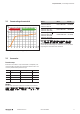
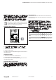
Pin assignments
I/O connections
M8, 3-pole 8DI 8DIO
4
3 1
1 24V 24V
3 GND GND
4 In In/Out
Power supply
M12, 5-pole 8DI 8DIO
2
4
5
3
1
1 n.c. 24VDC ± 25%
2 24VDC ± 25% 24VDC ± 25%
3
internally bridged
GND
GND
4 GND
5 FE FE
ATTENTION
Product can be destroyed!
▶ Please do never position the power supply (24VDC) at
the signal or data lines (pin 1 to pin4).
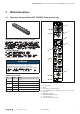
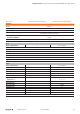
PROFIBUS-DP
M12, 5-pole, B-coded Signal Function
2
4
5
3
1
Male IN
2
4
5
3
1
Female OUT
1 VP
1)
+5V
2 RxD/TxD- N Channel A
3 DGND (0V)
1)
GND
4 RxD/TxD- P Channel B
5 n.c. FE
1) Internal signals that can be used to supply a terminating resistor (OrderNo.
1784770000). They may never be wired up or forwarded to other partici-
pants.