
User Documentation


de
Bedienungsanleitung
VPU AC I 275/25 LCF S
en
Operating instructions
VPU AC I 275/25 LCF S
fr
Mode d’emploi
VPU AC I 275/25 LCF S
it
Istruzioni per l’uso
VPU AC I 275/25 LCF S
es
Instrucciones de empleo
VPU AC I 275/25 LCF S
zh
使用说明
VPU AC I 275/25 LCF S
nl
Gebruiksaanwijzing
VPU AC I 275/25 LCF S
Weidmüller Interface GmbH & Co. KG
Klingenbergstraße 26
32758 Detmold, Germany
T +49 5231 14-0
F +49 5231 14-292083
www.weidmueller.com
Type 1
Class I
Type 2
Class II
Type 3
Class III
LPZ 1 LPZ 2
LPZ 3
LPZ 0A
Series:
VPU I
VPU I LCF
VPU AC I
VPU AC I LCF
Series:
VPU II
VPU AC II
Series:
VPU II
VPU III
F1
F2
PEN
L3
L1
L2
VPU
4 wire Net / Grid (TN-C)
F1
F2
VPU
PE
N
L3
L1
L2
3+1 connection (TT or TN-C-S)
F1
F2
PE
N
L3
L1
L2
VPU
5 wire Net / Grid (TN-C-S)
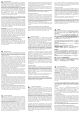
Technische Daten / Technical specications / Caractéristiques techniques / Dati tecnici / Datos técnicos / 技术数据 / Technische
gegevens
A
Montage und Demontage / Mounting and demounting / Montage et démontage / Montaggio è smontaggio / Montaje y desmontaje / 安装
和拆卸 / Montage en demontage
B
Überwachung und Wartung / Monitoring and maintenance / Surveillance et maintenance / Controllo e manutenzione / Monitorización y
mantenimiento / 监控和维护 / Bewaking en onderhoud
C
Anwendung / Application / Application / Applicazione / Aplicación / 应用 / Toepassing
D
PE-Verkabelung / PE cabling / Câblage PE / Cablaggio PE /
Cableado PE / PE 布线 / PE-bekabeling
E
Koordination / Coordination / Coordination / Coordinamento /
Coordinación / 协调 / Coördinatie
IEC 62305-4
F
VPU AC I (R) 275/25 LCF S (2PE) (2N)
N-PE L-N
Type 305 V 240 V
IEC/EN 61643-11
Grid (U
n
) @ 50...60 Hz
0 V
N-PE spark gap
230/400 V
TN, TT
Voltage regulation ±10 % ±10 %
U
n
0 V 240 V
I
n
/ I
max
(8/20 µs) 100/150 kA 25/65 kA
I
PE
5 µA 5 µA
I
imp
100 kA 25 kA
I
SCCR
– 50 kA
I
100 A 50 kA
U
p
@ I
n
≤ 1500 V ≤ 1500 V / ≤ 1700 V
3)
U
c
305 V 275 V
TOV
(N-PE: 200 ms,
L-N: 120 minutes)
1200 V 442 V
Wire cross-section min.
2.5 mm
2
(AWG14) 2.5 mm
2
(AWG14) 2.5 mm
2
(AWG14) l = 15 mm / 4.5 Nm
Wire cross-section max.
35 mm
2
(AWG2) 35 mm
2
(AWG2) l = 15 mm / 4.5 Nm
R (Remote signal contact)
1)
AC: 250 V / 1 A DC: 24 V / 0.5 A 1CO 0.25...1.5 mm
2
(AWG24...16) l = 8 mm
T
A
-40 °C...+85°C
Relative humidity 5...95 %, indoor
Altitude 4000 m
Protection degree IP20, built-in
Number of ports 1
Dimensions a x b
2)
x c
(single device)
110.5 x (1 HP) x 86 mm
Approvals / applied standards /
directives
CE, IEC/EN 61643-11
Spare arrester 2726810000 2726820000
1) R = remote signal contact (BCZ 3.81/3/180 1792780000)
2) horizontal pitch (HP), 1 HP = 18 mm
3) VPU AC I 3+1 275/25 LCF S 2PE
VPU AC I 3+1 R 275/25 LCF S 2PE
VPU AC I 0 275/25 LCF S 2PE
1
2
1
2
3
a / b / c
de
Höhe / Breite / Tiefe
en
Height / Width / Depth
fr
Hauteur / Largeur / Profondeur
it
Altezza / Larghezza / Profondità
es
Altura / Ancho / Profundidad
zh
高/宽/深
nl
Hoogte / Breedte / Diepte
a
bc
Abb. / Fig. B1 Abb. / Fig. B2
1
2
VPU AC I
VPU AC I
ü
û
grün / green / verte / verde / verde /
绿色/groen
rot / red / rouge / rosso / rojo / 红
色/rood
Sicherungen / Fuses / Coupe-circuits / Fusibili / Fusibles / 保
险丝 / Zekeringen
G
I
SCCR
F1 → F2
50 kA
F1 ≤ 315 A gG → F2 = not needed
F1 > 315 A gG → F2 ≤ 315 A gG
Tab. / Tab. G
a + b ≤ 0.5
m
b
a
SPD
Fuse
b ≤ 0.5 m
b
SPD
Fuse
Device
Device
Abbildung ähnlich / Illustration similar
14 11 12
R
1)
14 11 12
R
1)
2728370000/00/03-2020