
Brochure/Catalogue

Components for Surge protection
Components for Surge protection
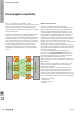
Surge protection devices (SPDs)
There is no ideal component that can full all the technical
requirements of surge protection equally effectively. Instead,
we use a variety of components with different physical
methods of operation that complement each other; these
possess distinct protective effects. Super-fast reaction time,
high current-carrying capacity, low residual voltage and long
service life cannot be found in one single component.
In practice we use three principal components:
1. spark gaps
2. varistors
3. suppression diodes
Therefore, to optimise the surge protection solution, carefully
matched groups of these components are often combined in
one protective module.
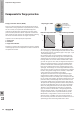
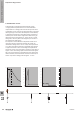
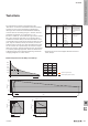
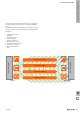
1. Spark gaps / GDT
Pulse form shape without GDT Pulse form shape with GDT
The name says it all. High voltages are discharged to earth
via a spark gap (e.g. gas discharge tube) that has been red.
The discharge capacity of sparkover gaps is very high – up to
100 kA depending on type.
Gas sparkover gaps are incorporated in insulating glass or
cera mic (aluminium oxide) housings. The electrodes of the
sparkover gap are made from a special alloy and placed in
housings which are vacuum sealed and lled with a noble
gas such as argon or neon. They are aligned with respect to
shape and clearance distance, so that the applied voltage
produces a distribution of eld strengths. This results in a
fairly precise voltage value for the complete ignition of the
spark gap. The housings are vacuum-tight and lled with an
inert gas such as argon or neon. The spark gap has a bipolar
function. The ignition voltage value, however, is dependent
on the steepness of the applied surge voltage.
The ignition characteristic curve for gas-lled spark gaps
reveals that the ignition voltages increase for those surge
voltages which climb more steeply. The consequence is that,
for very steep surge voltages, the ignition voltage (that is, the
protection level) is relatively high and can be well in excess
of the rated voltage for the spark gap (approx. 600–800 V).
The problematic quenching behaviour of the red sparkover
gap can be a disadvantage. The arc has a very low voltage
and is only extinguished when the value drops below this.
Therefore, when designing the geometry of a sparkover
gap, care is taken to ensure that – through long distances
and also through cooling – the voltage of the arc remains
as high as possible and so is quenched relatively quickly.
Nevertheless, a longer follow current can ensue. This can
draw its energy, in addition, from the incoming supply of
the circuit to be protected. One effective solution is to wire a
sparkover gap and a fast-acting fusible link in series.
Possible types:
Blow-out spark gap
Encapsulated spark gap
Gas-lled spark gap
U (kV)
1.0
0.5
1 µs
t
U (kV)
1.0
0.5
1 µs
t
W
The basics of lightning and surge protection
W.28 2028840000