
Brochure/Catalogue


General installation advice
General installation advice
Many details have to be taken into account during the
installation of surge protection and the electrical system in
order to achieve optimum protection.
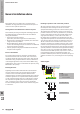
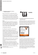
Arrangement and subdivision of electrical panel
Steel cabinets possess good magnetic shielding properties.
The following points should be taken into consideration
during the installation:
• Avoid unnecessarily long lines
(particularly lines with a high volume of data trafc).
• Route sensitive signalling lines separately from lines with
a high interference potential.
• Route shielded lines directly to the equipment and
connect the shielding there (do not connect via additional
terminal in switching cabinet).
• Classify equipment in groups with different sensitivities
and place these together.
Place of installation
The surge protection devices should be mounted where
the lines and cables enter the cabinet. This is the lowest
mounting rail directly above the cable entries. This prevents
interference being coupled within the cabinet; interference
is discharged right at the entry to the cabinet. When using
shielded lines, these can be connected at this point by using
Weidmüller clamp straps.
Routing the lines
Signalling lines should be laid within the system/cabinet
over the shortest route to the surge protection and then
continue to the connected equipment. Protected and
unprotected lines should be routed separately. The earth line
should be regarded as an unprotected line. Metal partitions
can be used along cable routes or in cable ducts to achieve
this separation. If signalling lines are laid parallel to power
lines, a clearance of min. 500 mm must be maintained.
The best shielding offers metallic cable conduits along with
a metal cover.
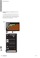
Earthing of products and connected products
All surge protection devices have an earth-connection
terminal point. The earthing wire for the associated
equipotential bonding rail must be connected to this point.
The earthing wire should have as large a cross-section as
possible and also be as short as possible. Every centimetre
of extra cable length increases the residual voltage of the
surge protection device (1 metre / 39 inch of cable = 1
kV voltage drop). In addition to the earthing terminal, the
surge protection products for measurement control systems
also offer the option of earthing via a DIN rail contact on a
TS 35. In order to achieve the best earth contact, the rail
should be mounted to an earthed metal back wall. In order
to obtain a lower protection level, the earthing terminal on
the surge protection products (for measurement and control
systems) should be connected to the equipotential bonding
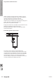
every 60 cm / 24 inch. According to IEC 62305, the PE
connection and the SPD spur may only be 0.5 m / 20 inch
to the lightning protection equipotential bonding. It is
possible to make the path as short as possible by using a so-
called V-connection or by connecting to the accompanying
PE.
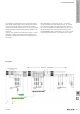
Cable lengths
L 1
L 2
L 3
N
PE
F1
F2
a
b
c
a + b ≤ 0.5 m / 20 inch
b ≤ 0.5 m / 20 inch
b
a
SPD
SPD
b
It is valid:
a + c ≤ 0.5 m / 20 inch
a + c ≤ 0.5 m / 20 inch,
then b is not relevant
W
The basics of lightning and surge protection
W.18 2028840000