
Brochure/Catalogue

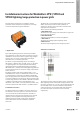

Surge protection installation instructions
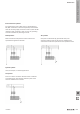
3.1 Connection to the phase conductor
and the neutral wire
When connecting cables to the VPU I/VPU II arresters,
normally the same wire cross-section is used both for the
phase conductors (L1, L2, L3) and the neutral wire (N). If
you need to reduce the cross-sections, then a protective
device (e.g. a main port fuse) should be used to protect the
connecting cables from short circuits. The terminals of the
arrester must not be used as branch terminals. The back-up
fuse for the VPU II can be be up to 200 A gL. For the VPU I, a
max. of 315 A gL can be selected for the back-up fuse.
Notes:
In the TN-CS power grid, 3-pole VPU IIs are used (on the
TN-C side). If the PEN conductor uses a separate PE and
N, then a 4-pole VPU II should be used (on the TN-S side).
According to DIN VDE 0100-534/A1 10/96, a VPU II 3+1-
280 V protector can be installed in a TT-type power grid.
For an IT grid with a 400 V phase-wire voltage, the
VPU II 3+1 385 V should be installed for 385 V.
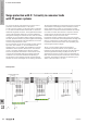
3.2 Connection to the earth
The earthing wire of the arrester is connected via the
shortest path to the earthing system of the consumer
installation. Longer connecting cables reduce the
effectiveness of the surge protection. They should not be
routed in parallel to other cables. An equipotential bonding
rail is available as a connection point in electrical consumer
systems with equipotential bonding. You must be certain
that the earthing for the arrester is connected to the earthing
system of the consumer installation.
In TN power grids, the PEN conductor and the earthing line
of the arrester should be connected to each other. The PEN
conductor from the electrical utility may not be used as the
earth.
If the PE or PEN rail on a distributor is used as the earthing
terminal, then the rail must be connected via a separate
earth wire to the earthing system of the consumer
installation.
Two ground terminals are provided in the VPU I. Both
terminal points must be connected. One leads to the
equipotential bonding connection on the building and the
other leads to the PE conductor on the installation. For Type I
lightning arresters, a conductor for carrying lightning current
must be used that is at least 16 mm². A minimum cross-
section of 4 mm² is required with Type II surge protection.
New standard: 6 mm²
IEC 60364-5-53 (VDE 0100-534): 2012
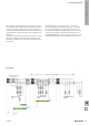
4 Installation of surge protection for end devices
(Type III arresters)
The VPU III or VPO-DS arrester is installed together with and
after the VPU II. The VPU III or VPO DS is built into the cable
that is to be protected. It can then protect a circuit up to 16
A. The VPU III can be installed in small distribution boards for
one circuit (e.g. for protecting monitors). The VPO DS can be
installed in devices or in cable conduits on-site.
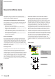
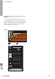
5 Functional check
It is important to visually inspect VPU lightning arresters and
surge protectors, especially during stormy weather. If the
colour of the viewing window changes or if the LED is red,
then the SPD must be replaced. As the varistors get older,
the temperature of the varistors may increase. In low-voltage
networks this can lead to re. Therefore all SPDs have a
built-in temperature monitoring mechanism that isolates the
varistor automatically from the power supply in the event of
danger. A signal or LED indicates that it has been switched
off. An additional switching contact (remote signalling
contact) reports this separation (this is labelled with R in all
product designations). The functionality of all VPU modules
can be tested using testing equipment (such as the V-TEST),
which is available separately.
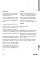
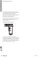
a + b ≤ 0.50 m
b
a
SPD
D
Vor Isolationsmessung trennen
oder Schutzelement ziehen!
EN
Before conducting isolation
measurement, remove plug-in
protective elements!
I
Prima di misurare l‘isolamento scollegare
il sezionatore o i fusibili di protezione!
FR
Avant toute mesure d’isolation déconnectez
les éléments de protection ou de séparation.
E
Antes de realizar la medición de aislamiento,
retirar el descargador.
CN
在做绝缘测试前 , 请先断开
保护回路或拔下保护模块!
1383210000/06/2012
W
The basics of lightning and surge protection
W.22 2028840000