Surge protection devices Catalogue 2016/2017 Let’s connect.
Dear Customers, The PDF versions of our catalogues offer practical additional functions, helping you to find your way around our product range and simplifying the ordering process. In addition to the catalogue, the PDF also contains: • Internal page links • Links to the online catalogue Try it out for yourself. Click the order number to obtain more detailed information and close-up images via you web browser. The links in the PDF file also enable you to go directly to the next desired catalogue page.
Surge Protection Devices Appendix 2028840000 Contents Surge Protection Devices Catalogue 4.
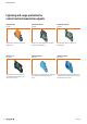
Product overview Lightning and surge protection for control and instrumentation signals II VARITECTOR SPC Page B.8 VARITECTOR SSC 6AN Page B.64 VARITECTOR SSC 4AN Page B.94 Pluggable surge protection for C&I circuits (IEC 61643-21) 2-stage surge protection with 6 screw connection for C&I circuits (IEC 61643-21) Pluggable surge protection for C&I circuits (IEC 61643-21) MCZ OVP series Page B.108 VARITECTOR SPC EX Page B.132 VARITECTOR SSC EX Page B.
Product overview Lightning and surge protection for low voltage facilities VPU I 35 kA series Page C.12 VPU I 25 kA series Page C.13 VPU I N-PE series Page C.
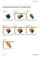
Product overview Lightning and surge protection for data interfaces IV VARITECTOR SPC Page D.4 V DATA CAT.6 Page D.12 VARITECTOR SSC 6AN Page D.14 Plug-in lightning and surge protection certified according to IEC 61643-21: for data ports (e.g. RS485) or high frequency (HF) signals Surge protection for 8 wires with RJ45 socket 2-stage lightning and surge protector with six screw connections: for data ports (e.g. RS485 and RS232) JPOVP CAT.6 Page D.17 COAX Page D.
Product overview Mains filter Wavefilter Page E.
VI 2028840000
A brief introduction to surge protection Contents A brief introduction to surge protection A brief introduction to surge protection 2028840000 Is surge protection worthwhile? A A.2 A.
A brief introduction to surge protection Is surge protection worthwhile? Is surge protection worthwhile? A You can rely on luck or take precautions The priority you give to surge protection depends on your willingness to take risks! Perhaps you think ”it’ll never happen to me”. You won‘t have lost anything, but you will also have gained little, if nothing at all, and you run the risk of a surge overvoltage at any time.
A brief introduction to surge protection Is surge protection worthwhile? Disaster from inside your premises Wherever electricity is used, it must also be switched on and off. The physical processes involved in a switching operation cause many surge overvoltages than those from the sky. Added to this are overvoltages caused by electrostatic discharges or faulty switching operations.
A A.
Lightning and surge protection for control and instrumentation signals Contents Lightning and surge protection for control and instrumentation signals Lightning and surge protection for control and instrumentation signals Lightning and surge protection for measurement and control systems intrinsically safe circuits (Ex zone) 2028840000 Quick selection guide B.2 SIL certification B.5 Lightning and surge protection for control and instrumentation signals B.6 VARITECTOR SPC B.8 V-TEST B.
Lightning and surge protection for control and instrumentation signals Quick selection guide Product quick selection for measurement and control signals Instrumentation and control equipment B Interface/ signal Mounting Connection system Protected Discharge Operating max.
Lightning and surge protection for control and instrumentation signals Quick selection guide Bus systems Interface/ signal Mounting Connection system Protected Discharge Operating max. wires capacity current voltage E1 EIB (European Installation Bus) ET 200 ET 200 Ethernet Cat.6 Ethernet Cat.
Lightning and surge protection for control and instrumentation signals Quick selection guide Product quick selection, information technology Telecommunications B B.4 Interface/ signal Mounting Connection system Protected Discharge Operating max. wires capacity current voltage ADSL ADVANT HDSL SHDSL T-DSL Telephone analogue TTY, 0(4) - 20 mA (Uk0-Bus) V.35 VDSL X.21/X.24 X.25/X.
SIL certification for VSSC and VSPC 2028840000 Lightning and surge protection for control and instrumentation signals SIL certification B B.
Lightning and surge protection for control and instrumentation signals SU RG EP RO TEC TI 0 1 2 3 4 5 MSR breakdowns or malfunctions can lead to exorbitant costs. As the standards covering low control voltages do not specify many parameters, the use of surge protection, apart from lightning protection zoning concepts, has to be classified according to type of signal, application circuit and the anticipated interference voltage phenomena.
Essential information for users can be found in the IEC 61643-22 standard (application standard for measurement and control signals) and in the IEC 62305-4 standard (application standard for installing internal lightning protection). It is important to determine which protection category is required. There are divisions for D1 (lightning protection), C2 (surge protection / overvoltage protection) and C1 (end device protection). These categories or classes are specified for the following products.
Lightning and surge protection for control and instrumentation signals VARITECTOR SPC VARITECTOR SPC Pluggable lightning and surge protection for measurement and control circuits Pluggable lightning and surge protection for 2 analogue signals or 4 binary signals in measurement/control circuits – with integrated error detection and alert functions in only 17.8 mm width. B Our pluggable VARITECTOR SPC surge protection is characterised by highest protective functions with compact dimensions.
Monitoring function Status display and message function: the protective function can be evaluated externally. Quick identification Colour-coded marking: simple identification of the different voltage levels in the switching cabinet.
Lightning and surge protection for control and instrumentation signals VARITECTOR SPC B VARITECTOR SPC Pluggable surge protection for the measurement and control industry VARITECTOR SPC Weidmüller's VARITECTOR SPC pluggable surge protection is remarkable for its combination of extremely high protective functionality and compact dimensions. It is suited for use in measurement and control circuits. The size is made possible by the seletion of INSTA dimensions, with a width of 17.8 mm (1TE).
Lightning and surge protection for control and instrumentation signals VARITECTOR SPC transfer the alert function to a 2-pole screw/plug-in connection in the bases and to the VSPC CONTROL UNIT. VSPC 1CL The VSPC 1CL is a two-stage protective combination with a gas discharge tube and a suppressor diode located between the current paths. This VSPC 1CL limits the surge voltage within one analogue signal circuit (such as for current loops).
Lightning and surge protection for control and instrumentation signals VARITECTOR SPC Applications B VSPC TAZ VSPC MOV The VSPC MOV 2CH and TAZ 2CH offer one-stage protection with a varistor (MOV) or suppressor diode (TAZ or TVS) between the current paths. This makes it possible to protect a no-voltage (floating) signal circuit. Two binary signal circuits can also be protected if terminals 1 and 7 are assigned to GND / PE. These VSPC pluggable components are inserted into the base (VSPC BASE 2/4CH).
Lightning and surge protection for control and instrumentation signals VARITECTOR SPC Test possibility / V-TEST Because the modules are pluggable, it is possible to test the VSPC visually or by using a V-TEST testing device. The VSPC can be easily tested; the user needs only to insert the VSPC pluggable component into the V-TEST. The result is then shown on the display. The VSPC R modules also feature an internal monitoring function for the arrester. An error is the displayed at the defective module.
Lightning and surge protection for control and instrumentation signals VARITECTOR SPC B Discharge capacity General technical data Accessories Testing is conducted using voltage and current pulses according to the IEC 61643-21 standard concerning surge protection in networks which process signals.
VARITECTOR SPC – Choice of device depending on the interface Interface Pluggable arrestor 0(4) … 20 mA 0(4) … 20 mA 0 … 10 V 0 … 10 V ADSL ADVANT ARCNET (Plus) ASI BITBUS BLN (Building Level Network) CAN-Bus C-BUS CC-LINK Data Highway (Plus), DH+ Datex-P DeviceNet DIN measurement bus Dupline/Miniplex EIB (European Installation Bus) ET 200 E1 FIPIO/FIPWAY Genius I/O Bus Hart HDSL IEC-BUS ISDN Basic connection (Uk0-Bus) Cathodic corrosion prevention LON™ (Works) LRE networks LUXMATE-Bus M-Bus (Remote readou
Lightning and surge protection for control and instrumentation signals VARITECTOR SPC VSPC 1CL - protection for one analogue signal • Optional monitoring function with status indicator and alert function • P luggable arrester (impedance-neutral plugging/unplugging without interruption) • C an be tested with the V-TEST testing device • O ptional version with floating earth PE connection to avoid voltage potential differences • U sable in accordance with installations standard IEC 62305 • T ested in a
Lightning and surge protection for control and instrumentation signals VARITECTOR SPC VSPC 1CL - arrester / plug-in elements Ordering data Rated voltage (AC) Rated voltage (DC) Max. continuous voltage, Uc (AC) Max.
Lightning and surge protection for control and instrumentation signals VARITECTOR SPC VSPC 1CL - protection for one analogue signal with remote alert • Optional monitoring function with status indicator and alert function • P luggable arrester (impedance-neutral plugging/unplugging without interruption) • C an be tested with the V-TEST testing device • O ptional version with floating earth PE connection to avoid voltage potential differences • U sable in accordance with installations standard IEC 623
Lightning and surge protection for control and instrumentation signals VARITECTOR SPC VSPC 1CL - arrester / plug-in components with remote alert Ordering data Rated voltage (AC) Rated voltage (DC) Max. continuous voltage, Uc (AC) Max.
Lightning and surge protection for control and instrumentation signals VARITECTOR SPC VSPC 2CL - protection for two analogue signals • Optional monitoring function with status indicator and alert function • P luggable arrester (impedance-neutral plugging/unplugging without interruption) • C an be tested with the V-TEST testing device • O ptional version with floating earth PE connection to avoid voltage potential differences • U sable in accordance with installations standard IEC 62305 • T ested in
Lightning and surge protection for control and instrumentation signals VARITECTOR SPC VSPC 2CL - arrester / plug-in elements Ordering data Rated voltage (AC) Rated voltage (DC) Max. continuous voltage, Uc (AC) Max.
Lightning and surge protection for control and instrumentation signals VARITECTOR SPC VSPC 2CL - protection for two analogue signals with remote alert • Optional monitoring function with status indicator and alert function • P luggable arrester (impedance-neutral plugging/unplugging without interruption) • C an be tested with the V-TEST testing device • O ptional version with floating earth PE connection to avoid voltage potential differences • U sable in accordance with installations standard IEC 62
Lightning and surge protection for control and instrumentation signals VARITECTOR SPC VSPC 2CL - arrester / plug-in components with remote alert Ordering data Rated voltage (AC) Rated voltage (DC) Max. continuous voltage, Uc (AC) Max.
Lightning and surge protection for control and instrumentation signals VARITECTOR SPC VSPC 2CL HF - protection for two analogue signals • Optional monitoring function with status indicator and alert function • P luggable arrester (impedance-neutral plugging/unplugging without interruption) • C an be tested with the V-TEST testing device • O ptional version with floating earth PE connection to avoid voltage potential differences • U sable in accordance with installations standard IEC 62305 • T ested
Lightning and surge protection for control and instrumentation signals VARITECTOR SPC VSPC 2CL HF - arrester / plug-in components Ordering data Rated voltage (AC) Rated voltage (DC) Max. continuous voltage, Uc (AC) Max.
Lightning and surge protection for control and instrumentation signals VARITECTOR SPC VSPC 2CL HF - protection for two analogue signals with remote alert • Optional monitoring function with status indicator and alert function • P luggable arrester (impedance-neutral plugging/unplugging without interruption) • C an be tested with the V-TEST testing device • O ptional version with floating earth PE connection to avoid voltage potential differences • U sable in accordance with installations standard IEC
Lightning and surge protection for control and instrumentation signals VARITECTOR SPC VSPC 2CL HF - arrester / plug-in components with remote alert Ordering data Rated voltage (AC) Rated voltage (DC) Max. continuous voltage, Uc (AC) Max.
Lightning and surge protection for control and instrumentation signals VARITECTOR SPC VSPC 1CL PW - combination of current loop protection and end device protection • Pluggable arrester (impedance-neutral plugging/unplugging without interruption) • C an be tested with V-TEST testing device • V ersion with floating-earth PE connection for avoiding voltage potential differences • U sable in accordance with installation standard IEC 62305 • T ested in accordance with IEC/EN 61643-21: D1, C1, C2, C3 • T
VSPC 1CL PW - arrester / plug-in components VSPC 1CL PW 24 V DC Ordering data Rated voltage (AC) Rated voltage (DC) Max. continuous voltage, Uc (AC) Max. continuous voltage, Uc (DC) Signalling contact B 34 V 24 V 27 V 38 V For Class III protection, green = OK; red = arrester is defective - replace 3 MHz ≤ 10 ms ≤ 0.
Lightning and surge protection for control and instrumentation signals VARITECTOR SPC VSPC 2SL - protection for two binary signals • Optional monitoring function with status indicator and alert function • P luggable arrester (impedance-neutral plugging/unplugging without interruption) • C an be tested with the V-TEST testing device • O ptional version with floating earth PE connection to avoid voltage potential differences • U sable in accordance with installations standard IEC 62305 • T ested in ac
Lightning and surge protection for control and instrumentation signals VARITECTOR SPC VSPC 2SL - arrester / plug-in components Ordering data Rated voltage (AC) Rated voltage (DC) Max. continuous voltage, Uc (AC) Max.
Lightning and surge protection for control and instrumentation signals VARITECTOR SPC VSPC 2SL - protection for two binary signals with remote alert • Optional monitoring function with status indicator and alert function • P luggable arrester (impedance-neutral plugging/unplugging without interruption) • C an be tested with the V-TEST testing device • O ptional version with floating earth PE connection to avoid voltage potential differences • U sable in accordance with installations standard IEC 6230
Lightning and surge protection for control and instrumentation signals VARITECTOR SPC VSPC 2SL - arrester / plug-in elements with remote alert Ordering data Rated voltage (AC) Rated voltage (DC) Max. continuous voltage, Uc (AC) Max.
Lightning and surge protection for control and instrumentation signals VARITECTOR SPC VSPC 4SL - protection for four binary signals • Optional monitoring function with status indicator and alert function • P luggable arrester (impedance-neutral plugging/unplugging without interruption) • C an be tested with the V-TEST testing device • O ptional version with floating earth PE connection to avoid voltage potential differences • U sable in accordance with installations standard IEC 62305 • T ested in a
Lightning and surge protection for control and instrumentation signals VARITECTOR SPC VSPC 4SL - arrester / plug-in elements Ordering data Rated voltage (AC) Rated voltage (DC) Max. continuous voltage, Uc (AC) Max.
Lightning and surge protection for control and instrumentation signals VARITECTOR SPC VSPC 4SL - protection for four binary signals with remote alert • Optional monitoring function with status indicator and alert function • P luggable arrester (impedance-neutral plugging/unplugging without interruption) • C an be tested with the V-TEST testing device • O ptional version with floating earth PE connection to avoid voltage potential differences • U sable in accordance with installations standard IEC 623
Lightning and surge protection for control and instrumentation signals VARITECTOR SPC VSPC 4SL - arrester / plug-in elements with remote alert Ordering data Rated voltage (AC) Rated voltage (DC) Max. continuous voltage, Uc (AC) Max.
Lightning and surge protection for control and instrumentation signals VARITECTOR SPC B VSPC 4 SL WIRE - protection for 3/4-wire signals • Protection of measuring bridge signals • P luggable arrester (impedance-neutral plugging/unplugging without interruption) • C an be tested with the V-TEST testing device • V ersion with floating-earth PE connection for avoiding voltage potential differences • S pace-saving design for 4 binary signals with optional alert function and no extra space required • U s
Lightning and surge protection for control and instrumentation signals VARITECTOR SPC VSPC 4SL WIRE - arrester / plug-in components Ordering data Rated voltage (AC) Rated voltage (DC) Max. continuous voltage, Uc (AC) Max.
Lightning and surge protection for control and instrumentation signals VARITECTOR SPC VSPC GDT - with sparkover gap (GDT) • Pluggable arrester (impedance-neutral plugging/unplugging without interruption) • C an be tested with the V-TEST testing device • V ersion with floating-earth PE connection for avoiding voltage potential differences • T ested in accordance with IEC 61643-21 • I ntegrated PE foot, safely discharges up to 20 kA (8/20 μs) and 2.
Lightning and surge protection for control and instrumentation signals VARITECTOR SPC VSPC GDT - arrester / plug-in components Ordering data Rated voltage (AC) Rated voltage (DC) Max. continuous voltage, Uc (AC) Max.
Lightning and surge protection for control and instrumentation signals VARITECTOR SPC VSPC MOV - protection with varistor • Pluggable arrester (impedance-neutral plugging/unplugging without interruption) • C an be tested with the V-TEST testing device • O ptional monitoring function with status display and alert functions for MOV components • V ersion with floating-earth PE connection for avoiding voltage potential differences • T ested in accordance with IEC 61643-21 • I ntegrated PE foot, safely di
Lightning and surge protection for control and instrumentation signals VARITECTOR SPC VSPC MOV - arrester / plug-in components VSPC MOV 2CH 24 V VSPC MOV 2CH 230 V VSPC MOV 2CH 24 V R VSPC MOV 2CH 230 V R 24 V 24 V 30 V 38 V 10 A 230 V 230 V 275 V 350 V 10 A Signalling contact No No 24 V 24 V 30 V 38 V 10 A UN 250 V AC 0.1 A 1CO at VSPC R with VSPC CONTROL UNIT 230 V 230 V 275 V 350 V 10 A UN 250 V AC 0.1 A 1CO at VSPC R with VSPC CONTROL UNIT Optical function display No No 14.
Lightning and surge protection for control and instrumentation signals VARITECTOR SPC B VSPC TAZ protection with suppressor diode • Pluggable arrester (impedance-neutral plugging/unplugging without interruption) • C an be tested with the V-TEST testing device • O ptional monitoring function with status display and alert functions for MOV components • L ower residual voltage • V ersion with floating-earth PE connection for avoiding voltage potential differences • T ested in accordance with IEC 61643
Lightning and surge protection for control and instrumentation signals VARITECTOR SPC VSPC TAZ - arrester / plug-in components VSPC TAZ 4CH 24 V Ordering data Rated voltage (AC) Rated voltage (DC) Max. continuous voltage, Uc (AC) Max.
Lightning and surge protection for control and instrumentation signals VARITECTOR SPC VSPC TELE UK0 - protection for telephones • Pluggable arrester (impedance-neutral plugging/unplugging without interruption) • C an be tested with the V-TEST testing device • T wo-wire input interface - Uko • Version with floating-earth PE connection for avoiding voltage potential differences • T ested in accordance with IEC 61643-21 • I ntegrated PE foot, safely discharges up to 20 kA (8/20 μs) and 2.
VSPC TELE UK0 - arrester/plug-in components VSPC TELE UK0 2 WIRE Ordering data Rated voltage (AC) Rated voltage (DC) Max. continuous voltage, Uc (AC) Max. continuous voltage, Uc (DC) Rated current IN Input attenuation Pulse-reset capacity Residual voltage, UP typical Protection level Wire-wire 1 kV/µs, typically Wire-wire 8/20 µs, typically Wire-PE 1kV/µs, typically Wire-PE 8/20 µs, typically Ordering data without function indicator Type Order No. Qty.
Lightning and surge protection for control and instrumentation signals VARITECTOR SPC VSPC RS485 - protection for data signals • Pluggable arrester (impedance-neutral plugging/unplugging without interruption) • C an be tested with V-TEST testing device • O ptional monitoring function with status indicator and alert functions • L ow residual voltage • V ersion with floating-earth PE connection for avoiding voltage potential differences • T ested in accordance with IEC 61643-21 • I ntegrated PE foot,
Lightning and surge protection for control and instrumentation signals VARITECTOR SPC VSPC RS485 - arrester / plug-in elements VSPC RS485 2CH Ordering data Rated voltage (AC) Rated voltage (DC) Max. continuous voltage, Uc (AC) Max.
Lightning and surge protection for control and instrumentation signals VARITECTOR SPC VSPC RS485 - protection for data signals with remote alert • Pluggable arrester (impedance-neutral plugging/unplugging without interruption) • C an be tested with the V-TEST testing device • O ptional monitoring function with status indicator and alert functions • L ower residual voltage • V ersion with floating-earth PE connection for avoiding voltage potential differences • T ested in accordance with IEC 61643-21
Lightning and surge protection for control and instrumentation signals VARITECTOR SPC VSPC RS485 - arrester / plug-in elements with remote alert VSPC RS485 2CH R Ordering data Rated voltage (AC) Rated voltage (DC) Max. continuous voltage, Uc (AC) Max. continuous voltage, Uc (DC) Rated current IN Signalling contact 5V 6.4 V 450 mA UN 250 V AC 0.1 A 1CO at VSPC R with VSPC CONTROL UNIT green = OK; red = arrester is defective - replace 113.
Lightning and surge protection for control and instrumentation signals VARITECTOR SPC Direct earthing VSPC BASE B UNPROTECTED PROTECTED 9 1 5 6 2 11 12 GND 10 9 GND 7 8 5 6 PE 4 3 PE 1 2 Similar to illustration TS PE Technical data Stripping length, rated connection Wire cross-section, stranded, min. Wire cross-section, stranded, max. Wire cross-section, solid, min. Wire cross-section, solid, max. Clamping range, rated connection, min. Clamping range, rated connection, max.
Indirect earthing Lightning and surge protection for control and instrumentation signals VARITECTOR SPC VSPC BASE / FG UNPROTECTED B PROTECTED 9 1 5 6 2 11 12 GND 10 9 GND 7 8 5 6 PE 4 3 PE 1 2 TS Similar to illustration PE Technical data Stripping length, rated connection Wire cross-section, stranded, min. Wire cross-section, stranded, max. Wire cross-section, solid, min. Wire cross-section, solid, max. Clamping range, rated connection, min. Clamping range, rated connection, max.
Lightning and surge protection for control and instrumentation signals VARITECTOR SPC Direct earthing, with remote alert B VSPC BASE / FG UNPROTECTED 7 11 PROTECTED 9 1 5 6 2 X2 X1 12 8 minus plus 11 12 GND 10 9 GND 7 8 5 6 PE 4 3 PE 1 2 X1 TS PE plus X2 minus Similar to illustration Technical data Stripping length, rated connection Wire cross-section, stranded, min. Wire cross-section, stranded, max. Wire cross-section, solid, min. Wire cross-section, solid, max.
Indirect earthing, with remote alert Lightning and surge protection for control and instrumentation signals VARITECTOR SPC VSPC BASE / FG UNPROTECTED 7 11 PROTECTED 9 1 5 6 2 X2 X1 12 B 8 minus plus 11 12 GND 10 9 GND 7 8 5 6 PE 4 3 PE 2 1 X1 TS PE plus X2 minus Similar to illustration Technical data Stripping length, rated connection Wire cross-section, stranded, min. Wire cross-section, stranded, max. Wire cross-section, solid, min. Wire cross-section, solid, max.
Lightning and surge protection for control and instrumentation signals VARITECTOR SPC VSPC accessories VSPC Ground • Can be applied to unassigned wires • Usable during start-up and maintenance • Earthing of all sensor cables • Can be plugged into standard base sockets B Technical data Rated voltage (DC) Max. continuous voltage, Uc (DC) Rated current Volume resistivity per path Type of connection Storage temperature Ambient temperature (operational) Rel.
The interlock mechanism on the VSPC Series pluggable arresters delivers extra reliability and an improved permanent contact under strong vibrating conditions. Lightning and surge protection for control and instrumentation signals VARITECTOR SPC VSPC Locking Clip B Technical data Colour Marking Function Weight Note Ordering data yellow Individually with a label Removal with screwdriver Snap-on by hand (press on) 10 g Type VSPC LOCKING CLIP Qty. 100 Order No.
Lightning and surge protection for control and instrumentation signals VARITECTOR SPC VSPC CONTROL UNIT 24 V DC • For monitoring up to 10 protective modules • Signalling module for all VSPCs with status indicator • Signalling of cable breaks / signal interruptions • Voltage supply from 18...31 V DC • Potential-free changeover contact • Function indicator (red/green LED) • Other NC-contact monitoring functions can be integrated into the signal circuit (e.g.
B 2028840000 B.
Lightning and surge protection for control and instrumentation signals V-TEST V-TEST Testing device from the VARITECTOR Series A testing device for pluggable surge protection: for testing in compliance with the IEC 62305-3 standard B The V-TEST is a compact, easily carried, testing device for pluggable protection modules from the VARITECTOR SPC family.
Lightning and surge protection for control and instrumentation signals V-TEST Quick and easy to operate It only takes a few simple menu steps (in German or English) to navigate directly to the measurement function. B Ensures timely testing intervals The portable V-TEST can be used to carry out repeated testing in compliance with IEC 62305-3.
Lightning and surge protection for control and instrumentation signals V-TEST B VSPC accessories V-TEST • Instrument for testing the protective functions of series: PU I, PU II and VSPC • Device for realising standard IEC 62305 (periodic testing) • Handy device with integrated battery set for local measurements • Result display via LCD display • Bilingual menu • Including protective bag and power supply • Intuitive user navigation in German and English The V-TEST is a compact, portable instrument for t
B 2028840000 B.
Lightning and surge protection for control and instrumentation signals VARITECTOR SSC 6AN B VARITECTOR SSC 6AN Lightning and surge protection in terminal block design Lightning and surge protection in 6 mm overall width for measurement and control circuits including isolation/ measuring function The VARITECTOR SSC combined surge protection, a direct PE contact function, separation of signal paths and operational status indication in one module. It is suitable for C&I applications.
Lightning and surge protection for control and instrumentation signals VARITECTOR SSC 6AN Simple and precise isolation The disconnect lever guarantees a simple signal path disconnection and a safe disconnect point that is easy to see. Fast identification Versatile marking options: markers for equipment and terminals and SNAPMARK markers that are easy to read in any installation position. B Testing and measuring To enable simple testing it is possible to insert the test plug (PS 2.
Lightning and surge protection for control and instrumentation signals VARITECTOR SSC 6AN B VARITECTOR SSC Surge protection in a terminal block: for measurement and control systems VARITECTOR SSC Weidmüller's VARITECTOR SSC series for surge protection (VSSC4 and VSSC6) is well suited for protecting measurement and control circuits. It features good protective functionality in a compact terminal-block design. This is due to its 6.2 mm width.
Lightning and surge protection for control and instrumentation signals VARITECTOR SSC 6AN VARITECTOR SSC The VSSC4 SL FG is a two-stage protective combination with a suppressor between the current paths and common return wire. The gas discharge tube to the PE provides a high-resistance earthing for the protective circuitry. Thus the protective circuitry can be operated with a floating earth. This VSSC4 SL FG limits the surge voltage in a binary floating signal circuit.
Lightning and surge protection for control and instrumentation signals VARITECTOR SSC 6AN B The VSSC6 TR LD GDT provides two-stage protection with two gas discharge tubes (GDT) between the current paths and common return wire. The VSSC6 GDT limits the surge voltage in two binary signal circuits and also has an isolator for each signal circuit. The VSSC6 TAZ provides one-stage protection with two suppressor diodes (TAZ) between the current paths and common return wire.
Lightning and surge protection for control and instrumentation signals VARITECTOR SSC 6AN VARITECTOR SSC Cate- Testing gory pulse C1 Quick rising edge Surge voltage 0,5 < 2 kV with 1.2/50 µs C2 Quick rising edge 2 < 10 kV 1 < 5 kA with with 1.2/50 µs 8/20 µs Quick rising edge ≥ 1 kV with 1 kV/µs 10 < 100 A 300 with 10/10.000 µs Surge voltage arrester High power ≥ 1 kV 0.5 < 2.5 kA 2 with 10/350 µs Arrester for lightning current and surge voltages C3 D1 Surge current 0.
Lightning and surge protection for control and instrumentation signals VARITECTOR SSC 6AN Quick product selection for the VARITECTOR SSC Technical data Interface 0(4) … 20 mA / 0 …10 V B B.70 Product designation Order No. VSSC4 CL 24 V UC 0.5 A 1063730000 VSSC6 CL 24 V UC 0.5 A 1064170000 VSSC6TR CL FG 24 V UC 0.5 A 1064310000 VSSC4 CL FG 24 V UC 0.5 A 1063770000 VSSC6 CL FG 24 V UC 0.5 A 1064270000 VSSC6TR CL FG 24 V UC 0.
B 2028840000 B.
Lightning and surge protection for control and instrumentation signals VARITECTOR SSC 6AN VSSC 6 CL and CL FG - protection for analogue signals • Two-stage surge protection with screw connection for measurement and control signals • S urge protection in terminal block design • Modular width of only 6.
Lightning and surge protection for control and instrumentation signals VARITECTOR SSC 6AN VSSC 6 CL and CL FG CL 12 V DC Ordering data Rated voltage (AC) Rated voltage (DC) Max. continuous voltage, Uc (AC) Max. continuous voltage, Uc (DC) Rated current IN Optical function display Isolating function Input attenuation Pulse-reset capacity Residual voltage, UP typical Ordering data Type Order No. Qty.
Lightning and surge protection for control and instrumentation signals VARITECTOR SSC 6AN VSSC 6 TR CL and TR CL FG - protection for floating current loops • Two-stage surge protection with screw connection for measurement and control signals • S urge protection in terminal block design • Modular width of only 6.
Lightning and surge protection for control and instrumentation signals VARITECTOR SSC 6AN VSSC 6TR CL and TR CL FG TR CL 12 V DC Ordering data Rated voltage (AC) Rated voltage (DC) Max. continuous voltage, Uc (AC) Max. continuous voltage, Uc (DC) Rated current IN Optical function display Isolating function Input attenuation Pulse-reset capacity Residual voltage, UP typical Ordering data Type Order No. Qty.
Lightning and surge protection for control and instrumentation signals VARITECTOR SSC 6AN VSSC 6 SL and SL FG - protection for binary signals with signal display • One-stage surge protection with screw connection for measurement and control signals • S urge protection in terminal block design • Modular width of only 6.
Lightning and surge protection for control and instrumentation signals VARITECTOR SSC 6AN VSSC 6 SL and SL FG SL LD 12 V DC Ordering data Rated voltage (AC) Rated voltage (DC) Max. continuous voltage, Uc (AC) Max. continuous voltage, Uc (DC) Rated current IN Optical function display Isolating function Input attenuation Pulse-reset capacity Residual voltage, UP typical Ordering data Type Order No. Qty.
Lightning and surge protection for control and instrumentation signals VARITECTOR SSC 6AN VSSC 6 TR SL and TR SL FG - protection for floating signals with signal display • Two-stage surge protection with screw connection for measurement and control signals with signal display • S urge protection in terminal block design • Modular width of only 6.
Lightning and surge protection for control and instrumentation signals VARITECTOR SSC 6AN VSSC 6 TR SL and TR CL FG TR SL LD 12 V DC Ordering data Rated voltage (AC) Rated voltage (DC) Max. continuous voltage, Uc (AC) Max. continuous voltage, Uc (DC) Rated current IN Optical function display Isolating function Input attenuation Pulse-reset capacity Residual voltage, UP typical Ordering data Type Order No. Qty.
Lightning and surge protection for control and instrumentation signals VARITECTOR SSC 6AN VSSC 6 MOV - protection with Varistor (MOV) • One-stage surge protection with screw connection for measurement and control signals • S urge protection in terminal block design • Modular width of only 6.
Lightning and surge protection for control and instrumentation signals VARITECTOR SSC 6AN VSSC 6 MOV MOV 12 V DC Ordering data Rated voltage (AC) Rated voltage (DC) Max. continuous voltage, Uc (AC) Max. continuous voltage, Uc (DC) Rated current IN Optical function display Isolating function Input attenuation Pulse-reset capacity Residual voltage, UP typical Capacitance Width Ordering data Type Order No. Qty. Note Ordering data Rated voltage (AC) Rated voltage (DC) Max.
Lightning and surge protection for control and instrumentation signals VARITECTOR SSC 6AN VSSC 6 TR LD MOV - protection with varistor (MOV) • One-stage surge protection with screw connection for measurement and control signals • S urge protection in terminal block design • Modular width of only 6.
Lightning and surge protection for control and instrumentation signals VARITECTOR SSC 6AN VSSC 6 TR LD MOV TR LD MOV 12 V DC Ordering data Rated voltage (AC) Rated voltage (DC) Max. continuous voltage, Uc (AC) Max. continuous voltage, Uc (DC) Rated current IN Optical function display Isolating function Input attenuation Pulse-reset capacity Residual voltage, UP typical Capacitance Width Ordering data Type Order No. Qty.
Lightning and surge protection for control and instrumentation signals VARITECTOR SSC 6AN VSSC 6 GDT - protection with sparkover gap (GDT) • One-stage surge protection with screw connection for measurement and control signals • S urge protection in terminal block design • Modular width of only 12.
Lightning and surge protection for control and instrumentation signals VARITECTOR SSC 6AN VSSC 6 GDT Ordering data Rated voltage (AC) Rated voltage (DC) Max. continuous voltage, Uc (AC) Max. continuous voltage, Uc (DC) Rated current IN Optical function display Isolating function Input attenuation Pulse-reset capacity Residual voltage, UP typical Capacitance Ordering data Type Order No. Qty.
Lightning and surge protection for control and instrumentation signals VARITECTOR SSC 6AN VSSC 6 TR GDT - protection with sparkover gap (GDT) • One-stage surge protection with screw connection for measurement and control signals • S urge protection in terminal block design • Modular width of only 6.2 mm or 12.
Lightning and surge protection for control and instrumentation signals VARITECTOR SSC 6AN VSSC 6 TR GDT Ordering data Rated voltage (AC) Rated voltage (DC) Max. continuous voltage, Uc (AC) Max. continuous voltage, Uc (DC) Rated current IN Optical function display Isolating function Input attenuation Pulse-reset capacity Residual voltage, UP typical Capacitance Ordering data Note 2028840000 Type Order No. Qty.
Lightning and surge protection for control and instrumentation signals VARITECTOR SSC 6AN VSSC 6 TAZ and TR TAZ - suppressor diode, with and without isolation option (TR) • Two-stage surge protection with screw connection for PROFIBUS RS422/485 data interfaces • S urge protection in terminal block design • Modular width of only 6.
Lightning and surge protection for control and instrumentation signals VARITECTOR SSC 6AN VSSC 6 TAZ and TR LD TAZ TAZ 12 V DC Ordering data Rated voltage (AC) Rated voltage (DC) Max. continuous voltage, Uc (AC) Max. continuous voltage, Uc (DC) Rated current IN Optical function display Isolating function Residual voltage, UP typical Capacitance Ordering data Note 2028840000 Type Order No. Qty. TAZ 24 V UC TR LD TAZ 24 V UC 15 V 12 A No No < 25 V 4.9 pF 24 V 34 V 30 V 42 V 12 A No No 62 V 0.
Lightning and surge protection for control and instrumentation signals VARITECTOR SSC 6AN VSSC 6 RS485 - protection for RS232/RS485 signal interfaces • Two-stage surge protection with screw connection for RS422/RS485 data interfaces • S urge protection in terminal block design • Modular width of only 6.
Lightning and surge protection for control and instrumentation signals VARITECTOR SSC 6AN VSSC 6 RS485, RS485 DP and RS232 Ordering data Rated voltage (AC) Rated voltage (DC) Max. continuous voltage, Uc (AC) Max. continuous voltage, Uc (DC) Rated current IN Optical function display Isolating function Input attenuation Pulse-reset capacity Residual voltage, UP typical Ordering data Note 2028840000 Type Order No. Qty. RS485 RS485 DP RS232 12 V 12 V 12 V 15 V 500 mA No No 113.
Lightning and surge protection for control and instrumentation signals VARITECTOR SSC 6AN VSSC 6 RTD - protection for PT100 signal interfaces • One-stage surge protection with screw connection for measurement and control signals • S urge protection in terminal block design • Modular width of only 6.
Lightning and surge protection for control and instrumentation signals VARITECTOR SSC 6AN VSSC 6 RTD RTD Ordering data Rated voltage (AC) Rated voltage (DC) Max. continuous voltage, Uc (AC) Max. continuous voltage, Uc (DC) Rated current IN Optical function display Isolating function Input attenuation Residual voltage, UP typical Ordering data Note 2028840000 Type Order No. Qty. B 1V 5V 300 mA No 113.6 MHz 126 V VSSC6 RTD 1139710000 10 End plate AP VSSC6 1063110000 B.
Lightning and surge protection for control and instrumentation signals VARITECTOR SSC 4AN B VARITECTOR SSC 4AN Lightning and surge protection in terminal block design The new and comprehensive surge protection family for measurement and control technology in 6 mm overall width The interfaces in C&I applications must be protected against surges, since coupling of surges on lines can interfere with or destroy signal inputs.
Large variety A solution for every type of surge protection: More than 100 variations: current loops and binary signals for 5 V, 12 V, 24 V, 48 V and 60 V, with integrated components, e.g. varistors. Lightning and surge protection for control and instrumentation signals VARITECTOR SSC 4AN B Quick identification Large-area marking options: marking of devices and single connections as well as colourcoded marking of the voltage levels for fast identification in the switching cabinet.
Lightning and surge protection for control and instrumentation signals VARITECTOR SSC 4AN VSSC 4 CL and CL FG - protection for current loops • Two-stage surge protection with screw connection for measurement and control signals • S urge protection in terminal block design • Modular width of only 6.
Lightning and surge protection for control and instrumentation signals VARITECTOR SSC 4AN VSSC 4 CL and CL FG VSSC4 CL 12 V DC 0.5 A Ordering data Rated voltage (AC) Rated voltage (DC) Max. continuous voltage, Uc (AC) Max. continuous voltage, Uc (DC) Rated current IN Optical function display Isolating function Input attenuation Pulse-reset capacity Residual voltage, UP typical Ordering data Type Order No. Qty. Note Rated voltage (AC) Rated voltage (DC) Max. continuous voltage, Uc (AC) Max.
Lightning and surge protection for control and instrumentation signals VARITECTOR SSC 4AN VSSC 4 SL and SL FG - protection for binary signal • Two-stage surge protection with screw connection for measurement and control signals • S urge protection in terminal block design • Modular width of only 6.
Lightning and surge protection for control and instrumentation signals VARITECTOR SSC 4AN VSSC 4 SL and SL FG VSSC4 SL 12 V DC 0.5 A Ordering data Rated voltage (AC) Rated voltage (DC) Max. continuous voltage, Uc (AC) Max. continuous voltage, Uc (DC) Rated current IN Optical function display Isolating function Input attenuation Pulse-reset capacity Residual voltage, UP typical Ordering data Type Order No. Qty. Note 2028840000 VSSC4 SL 60 V UC 0.
Lightning and surge protection for control and instrumentation signals VARITECTOR SSC 4AN VSSC 4 MOV - protection with Varistor (MOV) • One-stage surge protection with screw connection for measurement and control signals • S urge protection in terminal block design • Modular width of only 6.
Lightning and surge protection for control and instrumentation signals VARITECTOR SSC 4AN VSSC MOV 4 - components VSSC4 MOV 12 V DC Ordering data Rated voltage (AC) Rated voltage (DC) Max. continuous voltage, Uc (AC) Max. continuous voltage, Uc (DC) Rated current IN Optical function display Isolating function Requirements category acc. to IEC 61643-21 Pulse-reset capacity Residual voltage, UP typical Capacitance Ordering data Type Order No. Qty. Note Rated voltage (AC) Rated voltage (DC) Max.
Lightning and surge protection for control and instrumentation signals VARITECTOR SSC 4AN VSSC 4 GDT - protection with sparkover gap (GDT) • One-stage surge protection with screw connection for measurement and control signals • S urge protection in terminal block design • Modular width of only 12.
Lightning and surge protection for control and instrumentation signals VARITECTOR SSC 4AN VSSC 4 GDT - components Ordering data Rated voltage (AC) Rated voltage (DC) Max. continuous voltage, Uc (AC) Max. continuous voltage, Uc (DC) Rated current IN Optical function display Isolating function Residual voltage, UP typical Capacitance Ordering data Note 2028840000 Type Order No. Qty. VSSC4 GDT 110 V UC 20 kA VSSC4 GDT 240 V UC 20 kA 110 V 156 V 138 V 195 V 20 A No No 845 V 4.
Lightning and surge protection for control and instrumentation signals VARITECTOR SSC 4AN VSSC 4 TAZ - protection with suppressor diode (TAZ) • One-stage surge protection with screw connection for measurement and control signals • S urge protection in terminal block design • Modular width of only 6.
Lightning and surge protection for control and instrumentation signals VARITECTOR SSC 4AN VSSC 4 TAZ - components VSSC4 TAZ 12 V DC Ordering data Rated voltage (AC) Rated voltage (DC) Max. continuous voltage, Uc (AC) Max. continuous voltage, Uc (DC) Rated current IN Optical function display Isolating function Residual voltage, UP typical Capacitance Surge current-carrying capacity C3 Ordering data Note 2028840000 Type Order No. Qty. VSSC4 TAZ 24 V UC VSSC4 TAZ 48 V UC 15 V 20 A No No 22 V 5.
Lightning and surge protection for control and instrumentation signals VARITECTOR SSC 4AN VSSC 4 RC - protection with a combination of resistors and capacitors • Two-stage surge protection with screw connection for measurement and control signals • S urge protection in terminal block design • Modular width of only 12.
Lightning and surge protection for control and instrumentation signals VARITECTOR SSC 4AN VSSC 4 RC - components Ordering data Rated voltage (AC) Rated voltage (DC) Max. continuous voltage, Uc (AC) Max. continuous voltage, Uc (DC) Rated current IN Optical function display Isolating function Input attenuation Pulse-reset capacity Residual voltage, UP typical Capacitance Ordering data Note 2028840000 Type Order No. Qty.
Lightning and surge protection for control and instrumentation signals MCZ OVP series B MCZ OVP Lightning and surge protection for data interfaces Weidmüller’s “MCZ OVP” surge protection for industrial bus systems and data interfaces: Narrow surge-protection terminals with tension-clamp connections for PROFIBUS, Interbus, CAN, DeviceNet and LON™ – with no signal delay.
Lightning and surge protection for control and instrumentation signals MCZ OVP series Vibration-resistant PE contact Up to 10 kA (8/20 μs) of surge voltage can be reliably discharged via the stainless steel Omega spring. This contact snaps onto the rail and requires no tools to install. B High transfer rates with protection Variants are available for protecting data lines (including the following industrial bus systems: PROFIBUS, PROFINET, Interbus, C-Bus, MODBUS, LON™, CAN, DeviceNet, etc.
Lightning and surge protection for control and instrumentation signals MCZ OVP series B B.110 Narrow surge protection terminals with tension-clamp wire connections for measurement and control systems Weidmüller MCZ surge protection terminals are characterised by their maximum protective function, and a compact design of only 6 mm. The tension spring connection and direct earthing via the terminal rail contact results in time-savings during installation.
Lightning and surge protection for control and instrumentation signals MCZ OVP series MCZ OVP SL FG is a three-stage protective combination with two suppression diodes, each from the signal line to earth. It limits the surge in binary circuits, e.g. for actuators. A high-resistance earth connection is achieved with three gas discharge tubes. B Derating curve MCZ OVP Imax = 0,5 A Derating curve Loading current in A 0.60 0.50 mounted on rail without clearance mounted on rail with clearance 20 mm 0.40 0.
Lightning and surge protection for control and instrumentation signals MCZ OVP series 2-stage protection with tension clamp connection MCZ OVP HF 5 V 0.3 A MCZ OVP HF 12 V 0.
2-stage protection with tension clamp connection Lightning and surge protection for control and instrumentation signals MCZ OVP series MCZ OVP HF 24 V 0.3 A • Slim overvoltage protection terminal with tension clamp connection • 6 mm slim fine overvoltage protection • F ast wiring thanks to TS contact and tension clamp connections R1 1 4 V2 V11 T1 V5 R2 2 V1 B V4 3 IN OUT 5 TS Technical data Rated voltage (AC) / Rated voltage (DC) Max. continuous voltage, Uc (AC) Rated voltage (DC), max.
Lightning and surge protection for control and instrumentation signals MCZ OVP series 3- or 1-stage protection with tension clamp connection MCZ OVP CL 24 V DC 0.5 A MCZ OVP CL 24 V AC 0.
3- or 1-stage protection with tension clamp connection MCZ OVP CL 24 V UC 1.25 A MCZ OVP SL 24 V DC 0.
Lightning and surge protection for control and instrumentation signals MCZ OVP series 3- or 1-stage protection with tension clamp connection MCZ OVP SL 24 V UC 1.25 A MCZ OVP CL 48 V UC 0.
3- or 1-stage protection with tension clamp connection MCZ OVP SL 48 V UC 0.5 A MCZ OVP CL 48 V UC 1.
Lightning and surge protection for control and instrumentation signals MCZ OVP series 3- or 1-stage protection with tension clamp connection MCZ OVP SL 48 V UC 1.25 A MCZ SL FG 24 V AC 0.
3- or 1-stage protection with tension clamp connection MCZ CL FG 24 V AC 0.5 A MCZ OVP 24 V 0.5 A Floating earth Filter Lightning and surge protection for control and instrumentation signals MCZ OVP series • Slim overvoltage protection terminal with tension clamp connection • 6 mm slim fine overvoltage protection • F ast wiring thanks to TS contact and tension clamp connections 1 3 1 4 5 2 TS 4 IN OUT 3 OUT 2 5 TS B IN Technical data Rated voltage (AC) Rated voltage (DC) Max.
Lightning and surge protection for control and instrumentation signals Earthing for shielded cables B Differences between earthing and shielding The terms “earthing” and “shielding” are classified according to their relation to human safety or facility safety. The earth is installed primarily to protect human life and for this reason is referred to as the protective earth conductor. On the other hand, shielding is used to ensure that the electrical system functions properly.
Lightning and surge protection for control and instrumentation signals Earthing for shielded cables Earthing for shielded cables Electrical and electronic systems should be designed and installed so that they are essentially protected against electrical interference, so that they also function reliably in the event of transient interference voltages. Electrical interference is introduced into circuits in many different ways. The most frequent cause is inductive interference effects.
Lightning and surge protection for control and instrumentation signals Earthing for shielded cables B Shielding In practice, the shield is often twisted and connected to a terminal point. There is very high attenuation (voltage drop) on these connections, especially for high-frequency interference. Therefore this type of shielding should not be used, even for short cable lengths. The cable shield is practically negated and can, at best, be helpful for lowfrequency interference.
Lightning and surge protection for control and instrumentation signals Earthing for shielded cables Effective shielding It is important to remember that the shielding should not be connected to the earth of the module connected, but rather to the protective earth (PE). In the case of modules mounted in an earthed, metal housing, the shielding must be connected to this housing. If an earthed housing is not available, the shielding must be connected to a separate earth.
Lightning and surge protection for control and instrumentation signals Installation advice for instrumentation and control engineering B Installation advice for instrumentation and control engineering The supply and earth lines to protective modules should be kept short in order to achieve optimum protection for equipment. The fuses for the protective modules should be chosen depending on the rated current as well as on the type of line and its route.
Lightning and surge protection for control and instrumentation signals Installation advice for instrumentation and control engineering Surge protection for binary signals The earthed DIN rail can then pick up the pulse and discharge it to the earth. The VSPC 4 SL plug-in surge protector can be used to protect the 24-V supply and also the 24-V switching signals. For long cables, and especially for current loops, additional protection is set-up at the sensors.
Lightning and surge protection for control and instrumentation signals Installation advice for instrumentation and control engineering B Surge protection for sensors with current loop output 0 (4)...20 mA The earthed DIN rail can then pick up the pulse and discharge it to the earth. VSPC 2CL plug-in surge protector for protecting two current loops with 0 (4)...20 mA. For long cables, and especially for current loops, additional protection is set-up at the sensors.
Lightning and surge protection for control and instrumentation signals Installation advice for instrumentation and control engineering Surge protection for sensors with supply voltage and a current loop 0 (4)...20 mA The unprotected side points in the direction where the pulse or interference is expected. The connecting cable’s shield is connected to terminal 3 e. g. the Weidmüller clamping bracket (KLBÜ) can be used. The earthed DIN rail can then pick up the pulse and discharge it to the earth.
Lightning and surge protection for control and instrumentation signals Installation advice for instrumentation and control engineering B Surge protection for sensors with 4-wire connection or temperature measurement The earthed DIN rail can then pick up the pulse and discharge it to the earth. The plug-in VSPC 3/4 surge protector is used to protect 3- or 4-wire measurement signals (e.g. from temperature sensors or load cells).
Lightning and surge protection for control and instrumentation signals Installation advice for instrumentation and control engineering Surge protection for telephone signals Uko The VSPC Uko plug-in surge protector is used to protect up to two phone lines with up to 4 wires. The unprotected side points in the direction where the pulse or interference is expected. The connecting cable’s shield is connected to terminal 3 e. g. the Weidmüller clamping bracket (KLBÜ) can be used.
Lightning and surge protection for control and instrumentation signals Installation advice for instrumentation and control engineering Surge protection for data lines, RS485 or RS422 B The VSPC RS485 plug-in surge protector is used to protect an RS485 data line or two RS422 data lines. The unprotected side points in the direction where the pulse or interference is expected. The connecting cable’s shield is connected to terminal 3 e. g. the Weidmüller clamping bracket (KLBÜ) can be used.
B 2028840000 B.
Lightning and surge protection for control and instrumentation signals VARITECTOR SPC EX B VARITECTOR SPC EX and ACT20X Pluggable surge protection and a universal signal converter for C&I signals in hazardous area applications Intrinsically safe circuits to limit energy are used in hazardous areas. In these circuits, the intrinsically safe signal converters with their galvanic isolation and Ex approved surge arresters provide excellent protection for sensitive control electronics.
Lightning and surge protection for control and instrumentation signals VARITECTOR SPC EX SPS B Hazardous area applications The ACT20X signal converter is approved for installation in zone 2 and converts signals from zones 0, 1 or 2 for the controller. The product is approved by ATEX, IECEx, and cULus Ex Div 1.
Lightning and surge protection for control and instrumentation signals VARITECTOR SPC EX VARITECTOR SPC EX Pluggable surge protection for measurement and control systems B VARITECTOR SPC EX Weidmüller’s VARITECTOR SPC EX pluggable surge protector is remarkable for its combination of extremely high protective functionality and compact dimensions. It protects intrinsically safe measurement and control circuits. The size is made possible by the selection of INSTA dimensions, with a width of 17.8 mm (1 TE).
Lightning and surge protection for control and instrumentation signals VARITECTOR SPC EX Products for intrinsically safe circuits VSPC 1CL 12 V ATEX and VSPC 1CL 24 V ATEX This VSPC surge protector is used to protect an intrinsically safe current loop. VSPC EX 1CL 5 V ATEX This VSPC EX surge protector is suitable for temperature signals which goes in and out of the intrinsically safe zone.
Lightning and surge protection for control and instrumentation signals VARITECTOR SPC EX B VARITECTOR SPC EX Discharge capacity General technical data Testing is conducted using voltage and current pulses according to the IEC 61643-21 standard concerning surge protection in networks which process signals. Storage temperature: -40 °C...+80 °C Operating temperature: -40 °C...70 °C Humidity: 5 %...
B 2028840000 B.
Lightning and surge protection for control and instrumentation signals VARITECTOR SPC EX B VSPC 1CL EX - protection for one analogue signal in intrinsically safe circuits • F or use in zones 2, 1, and 0 • P luggable arrester (impedance-neutral plugging/unplugging without interruption) • C an be tested with the V-TEST testing device • V ersion with floating-earth PE connection for avoiding voltage potential differences • C an be used in accordance with installation standard IEC 62305 as well as in AT
Lightning and surge protection for control and instrumentation signals VARITECTOR SPC EX VSPC 1CL EX - plug-in components / arrester Ordering data Rated voltage (AC) Rated voltage (DC) Rated current IN Optical function display Input attenuation Pulse-reset capacity Residual voltage, UP typical EX protection data Input voltage, max. Ui Internal capacity, max. CI Internal inductance, max. LI Input power, max.
Lightning and surge protection for control and instrumentation signals VARITECTOR SPC EX B VSPC 2CL EX – protection for two analogue signals in intrinsically safe circuits • For use in zones 2, 1, and 0 • P luggable arrester (impedance-neutral plugging/unplugging without interruption) • C an be tested with the V-TEST testing device • S pace-saving design for 3 analogue signals • V ersion with floating-earth PE connection for avoiding voltage potential differences • U sable in accordance with instal
VSPC 2CL EX - plug-in components / arrester VSPC 2CL 24 V DC EX Ordering data Rated voltage (AC) Rated voltage (DC) Rated current IN Optical function display Input attenuation Pulse-reset capacity Residual voltage, UP typical EX protection data Input voltage, max. Ui Internal capacity, max. CI Internal inductance, max. LI Input power, max.
Lightning and surge protection for control and instrumentation signals VARITECTOR SPC EX B VSPC 1CL PW EX - combinations in current loop signal and device protection in intrinsically safe circuits • Pluggable arrester (impedance-neutral plugging/unplugging without interruption) • C an be tested with the V-TEST testing device • V ersion with floating-earth PE connection for avoiding voltage potential differences • U sable in accordance with installations standard IEC 62305 • T ested in accordance wit
VSPC 1CL PW EX - plug-in components / arrester Ordering data VSPC 1CL PW 24 V EX Rated voltage (AC) Rated voltage (DC) Rated current IN 34 V 24 V 350 mA For Class III protection, green = OK; red = arrester is defective - replace 3 MHz ≤ 10 ms < 650 V Optical function display Input attenuation Pulse-reset capacity Residual voltage, UP typical EX protection data Input voltage, max. Ui Internal capacity, max. CI Internal inductance, max. LI Input power, max.
Lightning and surge protection for control and instrumentation signals VARITECTOR SPC EX B VSPC 2SL EX – protection for two binary signals in intrinsically safe circuits • For use in zones 2, 1, and 0 • P luggable arrester (impedance-neutral plugging/unplugging without interruption) • C an be tested with the V-TEST testing device • V ersion with floating-earth PE connection for avoiding voltage potential differences • C an be used in accordance with installation standard IEC 62305 as well as in ATEX
Lightning and surge protection for control and instrumentation signals VARITECTOR SPC EX VSPC 2SL EX - plug-in components / arrester Ordering data Rated voltage (AC) Rated voltage (DC) Rated current IN Optical function display Input attenuation Pulse-reset capacity Residual voltage, UP typical EX protection data Input voltage, max. Ui Internal capacity, max. CI Internal inductance, max. LI Input power, max.
Lightning and surge protection for control and instrumentation signals VARITECTOR SPC EX VSPC 4SL EX - protection for four binary signals in intrinsically safe circuits • For use in zones 2, 1, and 0 • P luggable arrester (impedance-neutral plugging/unplugging without interruption) • C an be tested with the V-TEST testing device • V ersion with floating-earth PE connection for avoiding voltage potential differences • U sable in accordance with installations standard IEC 62305 • T ested in accordance
Lightning and surge protection for control and instrumentation signals VARITECTOR SPC EX VSPC 4SL EX - plug-in components / arrester Ordering data Rated voltage (AC) Rated voltage (DC) Rated current IN Optical function display Input attenuation Pulse-reset capacity Residual voltage, UP typical EX protection data Input voltage, max. Ui Internal capacity, max. CI Internal inductance, max. LI Input power, max.
Lightning and surge protection for control and instrumentation signals VARITECTOR SPC EX B VSPC 3/4 SL WIRE EX - protection for 3/4-wire signals in intrinsically safe areas • Protection of measuring bridge signals in zones 0, 1 and 2 • P luggable arrester (impedance-neutral plugging/unplugging without interruption) • C an be tested with the V-TEST testing device • V ersion with floating-earth PE connection for avoiding voltage potential differences • C an be used in accordance with installation stan
VSPC 3/4SL WIRE EX- plug-in components / arrester VSPC 3/4 WIRE 5 V DC EX Ordering data Rated voltage (AC) Rated voltage (DC) Rated current IN Optical function display Input attenuation Pulse-reset capacity Residual voltage, UP typical EX protection data Input voltage, max. Ui Internal capacity, max. CI Internal inductance, max. LI Input power, max.
Lightning and surge protection for control and instrumentation signals VARITECTOR SPC EX Indirect earthing VSPC BASE 4SL FG EX Base element, indirect earthing via spark gap FG, floating earth for ATEX applications. B UNPROTECTED PROTECTED 9 1 5 6 2 11 12 GND 10 9 GND 7 8 5 6 PE 4 3 PE 1 2 TS Similar to illustration PE Technical data Stripping length, rated connection Wire cross-section, stranded, min. Wire cross-section, stranded, max. Wire cross-section, solid, min.
B 2028840000 B.
Lightning and surge protection for control and instrumentation signals VARITECTOR SSC EX B VARITECTOR SSC EX Lightning and surge protection for intrinsically safe circuits in the explosion hazard area When used in intrinsically safe circuits within EX zones 2 to 0, the VARITECTOR SSC can reliably protect measurement and control signals from lightning and surge voltages.
Lightning and surge protection for control and instrumentation signals VARITECTOR SSC EX Fast identification Versatile labelling: labels for equipment and individual connections, also easy to read SnapMark markers for any installation position. B Complete, standard compliant protection The VSSC EX prevents compensation currents ia the PE. It also complies with the over stress mode of the IEC 61643-21 standard.
Lightning and surge protection for control and instrumentation signals VARITECTOR SSC EX VARITECTOR SSC EX VARITECTOR SSC EX B 12.4-mm-wide lightning and surge protection for measurement and control signals in the Ex zone When used in intrinsically safe circuits within Ex zones 2 to 0, the VARITECTOR SSC can reliably protect measurement and control signals from lightning and surge voltages.
B 2028840000 B.
Lightning and surge protection for control and instrumentation signals VARITECTOR SSC EX B VSSC 4 CL FG EX - protection for floating earth, intrinsically safe current loops • 2-level surge protection with screw connection for intrinsically safe instrumentation and control signals • S urge protection in terminal block design •W idth of only 12.
Lightning and surge protection for control and instrumentation signals VARITECTOR SSC EX VSSC 4 CL FG EX Ordering data Rated voltage (AC) Rated voltage (DC) Rated current IN Optical function display Input attenuation Pulse-reset capacity Residual voltage, UP typical EX protection data Input voltage, max. Ui Internal capacity, max. CI Internal inductance, max. LI Input power, max. PI Ordering data Note 2028840000 Type Order No. Qty.
Lightning and surge protection for control and instrumentation signals VARITECTOR SSC EX VSSC 4 SL FG EX - protection for floating earth, binary, intrinsically safe signals • 2-stage surge protection. Screw connection for intrinsically safe measurement, control & feedback control signals • T erminal block design • Modular width of only 12.
Lightning and surge protection for control and instrumentation signals VARITECTOR SSC EX VSSC 4 SL FG EX Ordering data Rated voltage (AC) Rated voltage (DC) Rated current IN Optical function display Input attenuation Pulse-reset capacity Residual voltage, UP typical EX protection data Input voltage, max. Ui Internal capacity, max. CI Internal inductance, max. LI Input power, max. PI Ordering data Note 2028840000 Type Order No. Qty.
Lightning and surge protection for control and instrumentation signals VARITECTOR SSC EX VSSC 4 GDT EX - protection with sparkover gap (GDT) • One-stage surge protection with screw connection for measurement and control signals • S urge protection in terminal block design • Modular width of only 12.
Lightning and surge protection for control and instrumentation signals VARITECTOR SSC EX VSSC 4 GDT EX VSSC4 GDT 55 V UC 20 kA EX Ordering data 55 V 38 V 300 mA No 4.65 pF ≤ 1800 V Rated voltage (AC) Rated voltage (DC) Rated current IN Optical function display Capacitance Residual voltage, UP typical EX protection data Input voltage, max. Ui Internal capacity, max. CI Internal inductance, max. LI Input power, max. PI Ordering data Note 2028840000 B 55 V 0 nF 0 µH 0.75 W Type Order No. Qty.
Lightning and surge protection for control and instrumentation signals VARITECTOR SSC EX B VSSC 6 TR FG EX - protection for floating, intrinsically safe current loops with isolator function • 2-level surge protection with screw connection for intrinsically safe instrumentation and control signals • S urge protection in terminal block design • A lignment width of only 12.
Lightning and surge protection for control and instrumentation signals VARITECTOR SSC EX VSSC 6 TR FG EX Ordering data Rated voltage (AC) Rated voltage (DC) Rated current IN Optical function display Input attenuation Pulse-reset capacity Residual voltage, UP typical EX protection data Input voltage, max. Ui Internal capacity, max. CI Internal inductance, max. LI Input power, max. PI Ordering data Note 2028840000 Type Order No. Qty.
Lightning and surge protection for control and instrumentation signals VARITECTOR SSC EX B VSSC 6 RS485 PROFIBUS PA - protection for RS422/485 intrinsically safe signal interfaces • Two-stage surge protection with screw connection for PROFIBUS PA RS422/485 data interfaces • S urge protection in terminal block design • Modular width of only 6.
Lightning and surge protection for control and instrumentation signals VARITECTOR SSC EX VSSC 6 RS485 PROFIBUS PA VSSC6 RS485 PA EX Ordering data Rated voltage (AC) Rated voltage (DC) Rated current IN Optical function display Input attenuation Pulse-reset capacity Residual voltage, UP typical EX protection data Input voltage, max. Ui Internal capacity, max. CI Internal inductance, max. LI Input power, max. PI Ordering data Note 2028840000 B 12 V 300 mA No 113.
Lightning and surge protection for control and instrumentation signals VARITECTOR SSC EX VSSC 6 RTD EX - protection for intrinsically safe PT100 signal interfaces • Two-stage surge protection with screw connection for intrinsically safe PT100/PT1000 signals • S urge protection in terminal block design • Modular width of only 12.
Lightning and surge protection for control and instrumentation signals VARITECTOR SSC EX VSSC 6 RTD EX VSSC6 RTD EX Ordering data Rated voltage (AC) Rated voltage (DC) Rated current IN Optical function display Input attenuation Pulse-reset capacity Residual voltage, UP typical EX protection data Input voltage, max. Ui Internal capacity, max. CI Internal inductance, max. LI Input power, max. PI Ordering data Note 2028840000 B 1V 300 mA No 120 Mhz ≤ 10 ms ≤ 1650 V 5V 7 nF 0 µH 0.75 W Type Order No.
Lightning and surge protection for control and instrumentation signals ATEX and IEC Ex approvals B.
Approval – VSSC-ATEX 2028840000 Lightning and surge protection for control and instrumentation signals ATEX and IEC Ex approvals B B.
Lightning and surge protection for control and instrumentation signals ATEX and IEC Ex approvals B.
Approval – VSPC-IEC Ex 2028840000 Lightning and surge protection for control and instrumentation signals ATEX and IEC Ex approvals B B.
Lightning and surge protection for control and instrumentation signals ATEX and IEC Ex approvals B.
Lightning and surge protection for low voltage supply Contents Lightning and surge protection for low voltage facilities Lightning and surge protection for low voltage facilities 2028840000 Quick selection guide C.2 Type I and II lightning arrester C.8 Type II surge protection C.30 Lightning and surge protection for photovoltaic systems on the DC side C.52 Type III surge protection for end devices C.58 C C.
Lightning and surge protection for low voltage supply Quick selection guide Product quick selection, power supply Type I Product Type I - LCF 35 kA VPU I 1 R LCF 280V/35kA VPU I 1 LCF 280V/35kA VPU I 1 R LCF 400V/35kA VPU I 1 LCF 400V/35kA Type I - LCF 25 kA / 280 V VPU I 1 R LCF 280V/25kA VPU I 1 LCF 280V/25kA VPU I 2 R LCF 280V/25kA VPU I 2 LCF 280V/25kA VPU I 3 R LCF 280V/25kA VPU I 3 LCF 280V/25kA VPU I 4 R LCF 280V/25kA VPU I 4 LCF 280V/25kA VPU I 1+1R LCF 280V/25kA VPU I 1+1 LCF 280V/25kA VPU I 3+
Lightning and surge protection for low voltage supply Quick selection guide Type I Product Type I - 12.5 kA / 280 V VPU I 1 280V/12.5kA VPU I 1 R 280V/12.5kA VPU I 2 280V/12.5kA VPU I 2 R 280V/12.5kA VPU I 4 280V/12.5kA VPU I 4 R 280V/12.5kA VPU I 3 280V/12.5kA VPU I 3 R 280V/12.5kA VPU I 3+1 280V/12.5kA VPU I 3+1R 280V/12.5kA VPU I 1+1 280V/12.5kA VPU I 1+1R 280V12.5kA Type I - 12.5 kA / 400 V VPU I 1 400V/12.5kA VPU I 1 R 400V/12.5kA VPU I 1+1 400V/12.5kA VPU I 1+1 R 400V12.5kA VPU I 3 400V/12.
Lightning and surge protection for low voltage supply Quick selection guide Product quick selection, power supply Type II Product Type II - 75 V VPU II 1 75V/30kA VPU II 1 R 75V/30kA VPU II 2 75V/30kA VPU II 2 R 75V/30kA Type II - 150 V VPU II 1 150V/40kA VPU II 1 R 150V/40kA VPU II 2 150V/40kA VPU II 2 R 150V/40kA VPU II 3 150V/40kA VPU II 3 R 150V/40kA VPU II 4 150V/40kA VPU II 4 R 150V/40kA Type II - 280 V VPU II 1 280V/40kA VPU II 1 R 280V/40kA VPU II 2 280V/40kA VPU II 2 R 280V/40kA VPU II 1+1 280V
Lightning and surge protection for low voltage supply Quick selection guide Type II Product Type II - 750 V VPU II 1 750V / 25kA VPU II 1 R 750V / 25kA VPU II 2 750V / 25kA VPU II 2 R 750V / 25kA VPU II 3 750V / 25kA VPU II 3 R 750V / 25kA VPU II 4 750V / 25kA VPU II 4 R 750V / 25kA VPU II 3+1 750V / 40kA VPU II 3+1 R 750V / 40kA Type II - N-PE VPU II 1 N-PE 260V/40kA 2028840000 Version Rated voltage Discharge capacity Protection level Uc Imax (8/20) 1-pole, separable 1-pole, separable 2-pole, s
Lightning and surge protection for low voltage supply Quick selection guide Product quick selection, power supply Type III Product Type III - TS 35 VPU III R 12V/4kV AC/DC VPU III R 24V/4kV AC/DC VPU III R 48V/4kV AC/DC VPU III R 120V/6kV AC/DC VPU III R 230V/6kV AC VPU III 3/280V AC Type III - SO LD VPU III SO LD VPU III SO LD+A C C.
Lightning and surge protection for low voltage supply Quick selection guide Product quick selection, power supply Lightning and surge protection for photovoltaic systems Product Typ I VPU I 2+0 R PV 1000V DC VPU I 2+0 PV 1000V DC VPU I 2+0 R PV 600V DC VPU I 2+0 PV 600V DC Typ II VPU II 2 PV 1000V DC VPU II 2 R PV 1000V DC VPU II 3 PV 1000V DC VPU II 3 R PV 1000V DC VPU II 2 PV 600V DC VPU II 2 R PV 600V DC VPU II 3 PV 1200V DC VPU II 3 R PV 1200V DC VPU II 3 PV 1500V DC VPU II 3 R PV 1500V DC 202884000
Lightning and surge protection for low voltage supply Type I and II lightning arrester VPU I lightning and surge protection Maximum type I protection from lightning and surges With the increase in limit values in standards, the introduction of IEC/EN 61643-11 in 2012 places great emphasis on the need for all-round, reliable surge protection. Our response to these new requirements is the new VPU lightning and surge protection series.
Type I and II lightning arrester Lightning and surge protection for low voltage supply Rapid status messaging The remote signaling contact with PUSH IN connection can be quickly connected and provides reliable information on the status of the protective function. Best overview The large, central, status window provides highly visible information on the status of the protective function. C Firmly locked in position You can hear and feel the arrester lock into the base.
Lightning and surge protection for low voltage supply Type I and II lightning arrester Type I Lightning / surge protection for type I with spark gaps and varistor technology: VPU I C Weidmüller‘s VPU I series offers type I surge protection featuring varistor technology with a leakage current capacity of 12.5 kA to 35 kA (10/350 µs). The pluggable, selfmonitoring surge arresters of up to 25 kA are optionally available as 1-, 2-, 3- or 4-pole versions – with or without a remote signalling contact.
Lightning and surge protection for low voltage supply Type I and II lightning arrester Electrical connection for building installation Dimensional drawing VPU I The type 1 VPU I series lightning arrester is connected between the external conductors (L1, L2, L3) and N/PE. The N/PE spark gap is produced with the VPU I LCF N-PE 50 kA or 100 kA. Cables as short as possible should be used. The maximum permissible operating voltage UC is 280 V AC. Decoupling to downstream type II arresters is not necessary.
Lightning and surge protection for low voltage supply Type I and II lightning arrester Type I and II lightning arrester VPU I 1/R LCF 280 V / 35 kA • No-leakage-current version suitable for use upstream of the electrical meter • Suitable with 35 kA (10/350 µs) for protective level I, II, III and IV (LPL I/II/III/IV) • Tested according to IEC 61643-11 for Type I and II surge protection • Can also be used as Type II surge protection VPU I 1/R LCF 400 V / 35 kA 1-phase / 1 / 1 2.
Type I and II lightning arrester VPU I 3/R LCF 280 V / 25 kA • No-leakage-current version suitable for use upstream of the electrical meter • Pluggable arrester • Suitable with 25 kA (10/350 µs) for protective level I, II, III and IV (LPL I/II/III/IV) • Tested according to IEC 61643-11 for Type I and II surge protection • Can also be used as Type II surge protection VPU I 4/R LCF 280 V / 25 kA TN-C L1 L1 TN-S L2 L2 OK CHANGE U 12 11 14 Lightning and surge protection for low voltage supply Ty
Lightning and surge protection for low voltage supply Type I and II lightning arrester Type I and II lightning arrester VPU I 3+1/R LCF 280 V / 25 kA • No-leakage-current version suitable for use upstream of the electrical meter • Pluggable arrester • Suitable with 25 kA (10/350 µs) for protective level I, II, III and IV (LPL I/II/III/IV) • Tested according to IEC 61643-11 for Type I and II surge protection • Can also be used as Type II surge protection TN-S, TT / / / / 2.
Type I and II lightning arrester VPU I 2/R LCF 280 V / 25 kA • No-leakage-current version suitable for use upstream of the electrical meter • Pluggable arrester • Suitable with 25 kA (10/350 µs) for protective level I, II, III and IV (LPL I/II/III/IV) • Tested according to IEC 61643-11 for Type I and II surge protection • Can also be used as Type II surge protection VPU I 1/R LCF 280 V / 25 kA 1-phase / / 1-phase / / 2.
Lightning and surge protection for low voltage supply Type I and II lightning arrester Type I and II lightning arrester VPU I 3/R 280 V / 25 kA VPU I 4/R 280 V / 25 kA • Pluggable arrester • Suitable with 25 kA (10/350 µs) for protective level I, II, III and IV (LPL I/II/III/IV) • Tested according to IEC 61643-11 for Type I and II surge protection • Can also be used as Type II surge protection • Field of application downstream of the main electrical meter / / / / 2.
Type I and II lightning arrester VPU I 3+1/R 280 V / 25 kA Lightning and surge protection for low voltage supply Type I and II lightning arrester VPU I 1+1/R 280 V / 25 kA • Pluggable arrester • Suitable with 25 kA (10/350 µs) for protective level I, II, III and IV (LPL I/II/III/IV) • Tested according to IEC 61643-11 for Type I and II surge protection • Can also be used as Type II surge protection • Field of application downstream of the main electrical meter / / / / 2.
Lightning and surge protection for low voltage supply Type I and II lightning arrester Type I and II lightning arrester VPU I 3/R 400 V / 25 kA • Suitable with 25 kA (10/350 µs) for protective level I, II, III and IV (LPL I/II/III/IV) • Pluggable arrester • Tested according to IEC 61643-11 for Type I and II surge protection • Can also be used as Type II surge protection • Field of application downstream of the main electrical meter TN-C L1 L1 1-phase L2 L2 OK CHANGE C VPU I 1/R 400 V / 25 kA
Type I and II lightning arresters Lightning and surge protection for low voltage supply Type I and II lightning arrester VPU I 4/R 400V / 25kA • Suitable with 25 kA (10/350 µs) for protective level I, II, III and IV (LPL I/II/III/IV) • Pluggable arrester • Tested according to IEC 61643-11 for Type I and II surge protection • Can also be used as Type II surge protection • Field of application downstream of the main electrical meter TN-S, TN C-S / / / / 2. &+$1*( 8 / / 2.
Lightning and surge protection for low voltage supply Type I and II lightning arrester Type I and II lightning arrester N-PE path Suitable for 230/400 V mains systems VPU I 1 N-PE 260 V / 50 kA VPU I 1 N-PE 260 V / 100 kA N-PE arrester 260 V N-PE arrester 260 V • Pluggable arrester • High energy absorption with short time to sparkover • Installation in distribution board C 1 1 3( 3( 3( 1 Technical data Rated voltage (AC) Max. continuous voltage, Uc (AC) Max.
Type I and II lightning arrester N-PE path Suitable for 400/690 V mains systems VPU I 1 N-PE 440 V / 50 kA Lightning and surge protection for low voltage supply Type I and II lightning arrester VPU I 1 N-PE 440 V / 100 kA N-PE arrester 440 V N-PE arrester 440 V • Tested according to IEC 61643-11 as Type I and Type II • Pluggable arrester • High energy absorption with short response time • Installation in distribution board 1 1 3( 1 C 3( 3( Technical data Rated voltage (AC) Max.
Lightning and surge protection for low voltage supply Type I and II lightning arrester Type I and II lightning arrester VPU I 3+1/R LCF 280 V / 12.5 kA • No-leakage-current version suitable for use upstream of the electrical meter • Pluggable arrester • Suitable for protective level III and IV (LPL III/IV) • Tested according to IEC 61643-11 for Type I and II lightning and surge protection • Can also be used as Type II surge protection TN-S, TT / / 2. &+$1*( C VPU I 1+1/R LCF 280 V / 12.
Type I and II lightning arrester VPU I 3/R LCF 280 V / 12.5 kA • No-leakage-current version suitable for use upstream of the electrical meter • Pluggable arrester • Suitable for protective level III and IV (LPL III/IV) • Tested according to IEC 61643-11 for Type I and II lightning and surge protection • Can also be used as Type II surge protection VPU I 1/R LCF 280 V / 12.5 kA TN-C L1 1-phase L2 OK CHANGE U 12 11 14 / L3 OK CHANGE U 2.
Lightning and surge protection for low voltage supply Type I and II lightning arrester Type I and II lightning arrester for use downstream of the electrical meter VPU I 4/R 280 V / 12.5 kA VPU I 3/R 280 V / 12.
Type I and II lightning arrester for use downstream of the electrical meter VPU I 2/R 280 V / 12.5 kA VPU I 1/R 280 V / 12.5 kA 1-phase • Suitable for protective level III and IV (LPL III/IV) • Pluggable arresters • Tested according to IEC 61643-11 for Type I and II lightning and surge protection • Can also be used as Type II surge protection 1-phase / L1 / 2. Lightning and surge protection for low voltage supply Type I and II lightning arrester 2.
Lightning and surge protection for low voltage supply Type I and II lightning arrester Type I and II lightning arresters for use downstream of an electric meter VPU I 3+1/R 280 V / 12.5 kA VPU I 1+1/R 280 V / 12.5 kA TN-S, TT • Suitable for protective level III and IV (LPL III/IV) • Pluggable arresters • Tested according to IEC 61643-11 for Type I and II lightning and surge protection • Can also be used as Type II surge protection / / 2. &+$1*( C 1-phase 8 / 2.
Type I and II lightning arresters for use downstream of an electric meter VPU I 4/R 400 V / 12.5 kA VPU I 3/R 400 V / 12.
Lightning and surge protection for low voltage supply Type I and II lightning arrester Type I and II lightning arresters for use downstream of an electric meter VPU I 1/R 400 V / 12.5 kA 1-phase • Suitable for protective level III and IV (LPL III/IV) • Pluggable arresters • Tested according to IEC 61643-11 for Type I and II lightning and surge protection • Can also be used as Type II surge protection L1 OK C CHANGE U 12 11 14 PE (N) Technical data Rated voltage (AC) Max.
Type I and II lightning arresters for use downstream of an electric meter VPU I 3+1/R 400 V / 12.5 kA VPU I 1+1/R 400 V / 12.
Lightning and surge protection for low voltage supply Type II surge protection VPU II surge protection Maximum type II protection from surges With the increase in limit values in standards, the introduction of IEC/EN 61643-11 in 2012 places great emphasis on the need for all-round, reliable surge protection. C Our response to these new requirements is the new VPU lightning and surge protection series.
Lightning and surge protection for low voltage supply Type II surge protection Solutions for PV photovoltaics VPU I and VPU II variants can be used in photovoltaic systems in accordance with IEC 50539-11. C Best overview The large, central, status window provides highly visible information on the status of the protective function.
Lightning and surge protection for low voltage supply Type II surge protection Surge protection for low-voltage consumer installations and electronics Surge protection of type II C The Weidmüller VPU II series surge protection protects low-voltage consumer installations and electronic devices against voltage surges that arise through, for example, atmospheric discharge (lightning) or switching activities (transients).
Lightning and surge protection for low voltage supply Type II surge protection LCF function Co-ordination with other arresters The leakage current free protection circuit (LCF function) is achieved by connecting the varistor and sparkover gap in series. This protection circuit is needed in the case of an insulation monitoring device, for example. The VPU II series can be installed with the following Weidmüller surge protection devices without decoupling.
Lightning and surge protection for low voltage supply Type II surge protection Type II/III surge protection Uc: 280 V Suitable for 230/400 V mains systems VPU II 4/R 280 V / 40 kA • Pluggable arrester • Coded voltage level • High energy absorption with short time to sparkover • Insert can be rotated through 180° • No follow-on current • Installation in distribution board • Thermal protection function • Co-ordination with VPU Type I TN-S L1 L2 OK C VPU II 3/R 280 V / 40 kA CHANGE U 12 11
Type II/III surge protection Uc: 280 V Suitable for 230/400 V mains systems VPU II 3+1/R 280 V / 40 kA • Pluggable arrester • Coded voltage level • High energy absorption with short time to sparkover • Insert can be rotated through 180° • No follow-on current • Installation in distribution board • Thermal protection function • Co-ordination with VPU Type I VPU II 1+1/R 280 V / 40 kA TN-S, TT L1 1-phase L2 OK U 12 11 14 CHANGE U L3 OK Lightning and surge protection for low voltage supply
Lightning and surge protection for low voltage supply Type II surge protection Type II/III surge protection Uc: 280 V Suitable for 230/400 V mains systems VPU II 2/R 280 V / 40 kA • Pluggable arrester • Coded voltage level • High energy absorption with short time to sparkover • Insert can be rotated through 180° • No follow-on current • Installation in distribution board • Thermal protection function • Co-ordination with VPU Type I VPU II 1/R 280 V / 40 kA 1-phase 1-phase L1 C U 12 11 14
Type II/III surge protection Uc: 280 V Suitable for 230/400 V mains systems VPU II 4 LCF/R 280 V / 40 kA • Leakage current free, pluggable arrester • Coded voltage level • High energy absorption with short time to sparkover • Insert can be rotated through 180° • No follow-on current • Installation in distribution board • Thermal protection function • Co-ordination with VPU Type I VPU II 3 LCF/R 280 V / 40 kA TN-S L1 L2 OK CHANGE U 12 11 14 U TN-C L3 OK CHANGE Lightning and surge protecti
Lightning and surge protection for low voltage supply Type II surge protection Type II/III surge protection Uc: 280 V Suitable for 230/400 V mains systems VPU II 1 LCF / R 280 V / 40 KA • Leakage current free, pluggable arrester • Coded voltage level • High energy absorption with short time to sparkover • Insert can be rotated through 180° • No follow-on current • Installation in distribution board • Thermal protection function • Co-ordination with VPU Type I 1-phase / 2.
Type II/III surge protection Uc: 400 V Suitable for stable 400/690 V mains systems • Pluggable arrester • Coded voltage level • High energy absorption with short time to sparkover • Insert can be rotated through 180° • No follow-on current • Installation in distribution board • Thermal protection function • Co-ordination with VPU Type I VPU II 4/R 400 V / 40 kA VPU II 3/R 400 V / 40 kA TN-S L1 L2 OK CHANGE U 12 11 14 U TN-C L3 OK Lightning and surge protection for low voltage supply Typ
Lightning and surge protection for low voltage supply Type II surge protection Type II/III surge protection Uc: 400 V Suitable for stable 400/690 V mains systems • Pluggable arrester • Coded voltage level • High energy absorption with short time to sparkover • Insert can be rotated through 180° • No follow-on current • Installation in distribution board • Thermal protection function • Co-ordination with VPU Type I VPU II 2/R 400 V / 40 kA VPU II 1/R 400 V / 40 kA 1-phase 1-phase L1 C U 12
Type II N-PE arrester Lightning and surge protection for low voltage supply Type II surge protection VPU II 1 N-PE • Tested according to IEC 61643-11 Type II • Pluggable N-PE arrester • Coded voltage level • High energy absorption with short time to sparkover • Insert can be rotated through 180° • Installation in distribution board N-PE arrester 260 V 1 C 3( Technical data Rated voltage (AC) Max. continuous voltage, Uc (AC) Max.
Lightning and surge protection for low voltage supply Type II surge protection Type II/III surge protection Uc: 150 V Suitable for 120/240 V mains systems VPU II 4/R 150 V / 40 kA • Pluggable arrester • Coded voltage level • High energy absorption with short time to sparkover • Insert can be rotated through 180° • No follow-on current • Installation in distribution board • Thermal protection function • Co-ordination with VPU Type I TN-S L1 TN-C L2 OK C VPU II 3/R 150 V / 40 kA U CHANGE
Type II/III surge protection Uc: 150 V Suitable for 120/240 V mains systems VPU II 2/R 150 V / 40 kA • Pluggable arrester • Coded voltage level • High energy absorption with short time to sparkover • Insert can be rotated through 180° • No follow-on current • Installation in distribution board • Thermal protection function • Co-ordination with VPU Type I VPU II 1/R 150 V / 40 kA 1-phase 1-phase L1 12 11 14 PE L1 N OK U Lightning and surge protection for low voltage supply Type II surge p
Lightning and surge protection for low voltage supply Type II surge protection Type II/III surge protection Uc: 75 V VPU II 2/R 75 V / 30 kA • Pluggable arrester • Coded voltage level • High energy absorption with short time to sparkover • Insert can be rotated through 180° • No follow-on current • Installation in distribution board • Thermal protection function VPU II 1/R 75 V / 30 kA 1-phase 1-phase L1 C U 12 11 14 PE L1 N OK CHANGE OK OK CHANGE CHANGE U U 12 11 14 PE (N) PE
C 2028840000 C.
Lightning and surge protection for low voltage supply Type II surge protection Type II/III surge protection Uc: 600 V Suitable for 600/1000 V mains systems VPU II 4/R 600 V / 25 kA • Pluggable arrester • Coded voltage level • High energy absorption with short time to sparkover • Insert can be rotated through 180° • No follow-on current • Installation in distribution board • Thermal protection function • Co-ordination with VPU Type I TN-S L1 TN-C L2 OK C VPU II 3/R 600 V / 25 kA CHANGE U
Type II/III surge protection Uc: 600 V Suitable for 600/1000 V mains systems VPU II 2/R 600 V / 25 kA • Pluggable arrester • Coded voltage level • High energy absorption with short time to sparkover • Insert can be rotated through 180° • No follow-on current • Installation in distribution board • Thermal protection function • Co-ordination with VPU Type I VPU II 1/R 600 V / 25 kA 1-phase 1-phase L1 U 12 11 14 PE L1 N OK Lightning and surge protection for low voltage supply Type II surge
Lightning and surge protection for low voltage supply Type II surge protection Type II/III surge protection Uc: 750 V Suitable for generator protection in wind turbines VPU II 4/R 750 V / 25 kA VPU II 3/R 750 V / 25 kA TN-S TN-C • Pluggable arrester • Coded voltage level • High energy absorption with short time to sparkover • Insert can be rotated through 180° • No follow-on current • Installation in distribution board • Thermal protection function • Co-ordination with VPU Type I / / 2.
Type II/III surge protection Uc: 750 V Suitable for generator protection in wind turbines Lightning and surge protection for low voltage supply Type II surge protection VPU II 3+1/R 750 V / 25 kA TN-S, TT, IT • Pluggable arrester • Coded voltage level • High energy absorption with short time to sparkover • Insert can be rotated through 180° • No follow-on current • Installation in distribution board • Thermal protection function • Co-ordination with VPU Type I 11 14 12 L1 L2 OK U CHANGE L3
Lightning and surge protection for low voltage supply Type II surge protection Type II/III surge protection Uc: 750 V Suitable for generator protection in wind turbines VPU II 2/R 750 V / 25 kA VPU II 1/R 750 V / 25 kA 1-phase 1-phase • Pluggable arrester • Coded voltage level • High energy absorption with short time to sparkover • Insert can be rotated through 180° • No follow-on current • Installation in distribution board • Thermal protection function • Co-ordination with VPU Type I / 1
Type II/III surge protection Uc: 1000 V Suitable for 1000 V mains systems Lightning and surge protection for low voltage supply Type II surge protection VPU II 1 / 1000 V 40 kA AC • Pluggable arrester • Coded voltage level • High energy absorption with short time to sparkover • Insert can be rotated through 180° • No follow-on current • Installation in distribution board • Thermal protection function Single-phase L1 OK CHANGE C U PE (N) Technical data Rated voltage (AC) Max.
Lightning and surge protection for low voltage supply Lightning and surge protection for photovoltaic systems on the DC side C AC DC DC surge protection for photovoltaic facilities For the DC voltage side, Weidmüller offers complete protection with a comprehensive range of surge arresters. For cable lengths of more than 10 m between the PV generator and the inverter, protection is needed at both ends. This means that both the generators and the inverter are protected.
Type I and II lightning arrester for use in photovoltaic applications • Suitable for protection level III and IV (LPL III/IV) • Can also be used as Type II surge protection • Tested in accordance with EN 50539-11 • Suitable for use in accordance with IEC 60364-7-712/ EN 50539-12 • Use if the separation distance cannot be observed VPU I 2+0 PV 600 V VPU I 2+0 PV 1000 V Photovoltaics Photovoltaics 2.
Lightning and surge protection for low voltage supply Lightning and surge protection for photovoltaic systems on the DC side Type II surge arrester for use in photovoltaic applications • Pluggable arrester • Suitable for protecting DC systems as Type II arrester • Encapsulated, non-blow-out arrester • Tested in accordance with EN 50539-11 • Pluggable arresters • Suitable for use in accordance with IEC 60364-7-712 / EN 50539-12 • Usage if the separation distance can be observed VPU II 2 PV/R 1000
Type II surge arrester for use in photovoltaic applications • Pluggable arrester • Suitable for protecting DC systems as Type II arrester • Encapsulated, non-blow-out arrester • Tested in accordance with EN 50539-11 • Pluggable arresters • Suitable for use in accordance with IEC 60364-7-712 / EN 50539-12 • Usage if the separation distance can be observed VPU II 2 PV/R 600 V VPU II 3 PV/R 1200 V Photovoltaics Photovoltaics + OK U 12 11 14 Lightning and surge protection for low voltage supply
Lightning and surge protection for low voltage supply Lightning and surge protection for photovoltaic systems on the DC side Type II surge arrester for use in photovoltaic applications • Pluggable arrester • Suitable for protecting DC systems as Type II arrester • Encapsulated, non-blow-out arrester • Tested in accordance with EN 50539-11 • Pluggable arresters • Suitable for use in accordance with IEC 60364-7-712 / EN 50539-12 • Usage if the separation distance can be observed VPU II 3 PV/R 1500V
C 2028840000 C.
Lightning and surge protection for low voltage supply Type III surge protection for end devices C VPU III surge protection for terminal devices Maximum type III protection from surges This product line provides an integrated protective strategy for surge protection for end devices. Rail-based mounting installations are especially important for industrial applications. For this reason, the housing design has been adapted to the standardised installation dimensions.
Best overview LEDs provide clearly visible information on the status of the protective function. Lightning and surge protection for low voltage supply Type III surge protection for end devices C Rapid status messaging The remote signalling contact provides reliable information regarding the status of the protective function. 2028840000 C.
Lightning and surge protection for low voltage supply Type III surge protection for end devices Type III surge protection for end devices Low-voltage consumer installations, small distribution units and electronics Surge protection module type III C Our surge protection modules VPU III and VPO DS protect low voltage consumer installations and electronic devices from voltage surges that occur through atmospheric discharge (lightning) or switching activities (transients).
Lightning and surge protection for low voltage supply Type III surge protection for end devices Dimensioned drawing VPU III Overall width 18 mm 102 90 45 L –40 °C...+70 °C –40 °C...+63 °C @ 230 V 50.5 70.5 71.5 VPU III device C N L PE N VPU III device –40 °C...+40 °C The standard implementation for operating the VPU III products is a series connection to the end device. Under this operational state, the protective device can bear a long-term load of 16 A.
Lightning and surge protection for low voltage supply Type III surge protection for terminal devices Type III with varistors / gas discharge tube VPU III R 230 V / 6 kV • Type III surge protection • Suitable for protecting terminals • Installed in the vicinity of the equipment to be protected • For mounting on rail TS 35 • Arrester with remote signalling contact • Tested in accordance with IEC 61643-11 VPU III R 120 V / 6 kV For use as device protector For use as device protector L L´ U C
Type III with varistors / gas discharge tube VPU III R 48 V / 4 kV • Type III surge protection • Suitable for protecting terminals • Installed in the vicinity of the equipment to be protected • For mounting on rail TS 35 • Arrester with remote signalling contact • Tested in accordance with IEC 61643-11 VPU III R 24 V / 4 kV For use as device protector For use as device protector L L´ 12 OK FAULT U 11 U N PE unprotected IN L L´ U Lightning and surge protection for low voltage supply T
Lightning and surge protection for low voltage supply Type III surge protection for terminal devices Type III with varistors / gas discharge tube VPU III R 12 V / 4 kV • Type III surge protection • Suitable for protecting terminals • Installed in the vicinity of the equipment to be protected • For mounting on rail TS 35 • Arrester with remote signalling contact • Tested in accordance with IEC 61643-11 VPU III SO LD / +A For use as device protector For use as device protector L L´ U C L 12
Type III with varistors Lightning and surge protection for low voltage supply Type III surge protection for terminal devices VPU III 3 / 280 V • Type III surge protection • Suitable for protecting 3-phase terminals • Installed in the vicinity of the equipment to be protected • For mounting on rail • Arrester with remote signalling contact • Tested in accordance with IEC 61643-11 For use as device protector / / 1 3( 21 )$8/7 8 8 8 / / / / 1 3( C Technical data Rated vo
C C.
Lightning and surge protection for data interfaces Contents Lightning and surge protection for data interfaces Lightning and surge protection for data interfaces Surge protection fundamentals for data signals D.2 Surge protection for data interfaces D.4 Installation instructions for data interfaces D.21 D 2028840000 D.
Surge protection for data interfaces The principles of data transmission Ring networks Four-wire systems The computers or data terminals are all connected to each other like a chain by means of, for example, coaxial cable. In this case the data is passed on from one data terminal to the next. Therefore, the entire ring is always under load.
Lightning and surge protection for data interfaces Surge protection fundamentals for data signals RS 232 Serial interface for point-to-point connections up to 20 kbit/s Voltage signal to earth: logic 1 (mark) -15 V to -3 V logic 0 (space) +3 V to +15 V max. signal level ±15 V Lines up to 20 m long depending on transmission rate. RS 232 COAX RS 422 RS485 Protection module in plug-in housing VSPC / RS485 Page D.8 Protection module in plug-in housing VSPC / RS485 VSPC / RS485 R Page D.8 Page D.
Lightning and surge protection for data interfaces Surge protection for data interfaces VSPC 2CL HF - protection for two analogue high-frequency signals • Optional monitoring function with status indicator and alert function • P luggable arrester (impedance-neutral plugging/unplugging without interruption) • C an be tested with the V-TEST testing device • O ptional version with floating earth PE connection to avoid voltage potential differences • U sable in accordance with installations standard IEC
Lightning and surge protection for data interfaces Surge protection for data interfaces VSPC 2CL HF - arrester / plug-in components Ordering data Rated voltage (AC) Rated voltage (DC) Max. continuous voltage, Uc (AC) Max.
Lightning and surge protection for data interfaces Surge protection for data interfaces VSPC 2CL HF - protection for two analogue high-frequency signals with remote alert • Optional monitoring function with status indicator and alert function • P luggable arrester (impedance-neutral plugging/unplugging without interruption) • C an be tested with the V-TEST testing device • O ptional version with floating earth PE connection to avoid voltage potential differences • U sable in accordance with installat
Lightning and surge protection for data interfaces Surge protection for data interfaces VSPC 2CL HF - arrester / plug-in components with remote alert Ordering data Rated voltage (AC) Rated voltage (DC) Max. continuous voltage, Uc (AC) Max.
Lightning and surge protection for data interfaces Surge protection for data interfaces VSPC RS 485 • Pluggable arrester (impedance-neutral plugging/unplugging without interruption) • C an be tested with V-TEST testing device • O ptional monitoring function with status indicator and alert functions • L ow residual voltage • V ersion with floating-earth PE connection for avoiding voltage potential differences • T ested in accordance with IEC 61643-21 • I ntegrated PE foot, safely discharges up to 20
VSPC RS485 - arrester / plug-in components VSPC RS485 2CH Ordering data Rated voltage (AC) Rated voltage (DC) Max. continuous voltage, Uc (AC) Max.
Lightning and surge protection for data interfaces Surge protection for data interfaces VSPC RS485 with remote alert • Pluggable arrester (impedance-neutral plugging/unplugging without interruption) • C an be tested with the V-TEST testing device • O ptional monitoring function with status indicator and alert functions • L ower residual voltage • V ersion with floating-earth PE connection for avoiding voltage potential differences • T ested in accordance with IEC 61643-21 • I ntegrated PE foot, safe
VSPC RS485 - arrester / plug-in components with remote alert VSPC RS485 2CH R Ordering data Rated voltage (AC) Rated voltage (DC) Max. continuous voltage, Uc (AC) Max. continuous voltage, Uc (DC) Rated current IN Signalling contact 5V 6.4 V 450 mA UN 250 V AC 0.1 A 1CO at VSPC R with VSPC CONTROL UNIT D green = OK; red = arrester is defective - replace 113.
Lightning and surge protection for data interfaces Surge protection for data interfaces V DATA Cat.6 surge protection for four wire pairs with RJ45 socket • RJ45 connection • A ll 4 wire pairs are protected • S turdy and compact metal housing • S uitable for Cat. 5 (up to 100 MHz) and Cat. 6 (up to 250 MHz, Class E) • S uitable for PoE+ (according to IEEE 802.3at) 5- ,1 D D.12 5- 287 Technical data Requirements category acc.
V DATA Cat.6 surge protection for four wire pairs with RJ45 socket V DATA CAT6 Ordering data Max. continuous voltage, Uc (AC) Rated current IN Insertion loss Protection level UP (typ.) Frequency range, max. Response time Volume resistance Wire-wire capacitance @ 1 MHz, 1 Vrms Wire-PE capacitance @ 1 MHz, 1 Vrms Ordering data Lightning and surge protection for data interfaces Surge protection for data interfaces Type Order No. Qty. 48 V 1A ≤ 1 dB @ 250 MHz ≤ 550 V 250 < 1 ns < 0.
Lightning and surge protection for data interfaces Surge protection for data interfaces VSSC 6AN RS485, RS485 DP and RS232 – for interface signals • Two-stage surge protection with screw connection for RS422/RS485 data interfaces • S urge protection in terminal block design • Modular width of only 6.
Lightning and surge protection for data interfaces Surge protection for data interfaces VSSC 6AN RS485, RS485 DP and RS232 Ordering data Rated voltage (AC) Rated voltage (DC) Max. continuous voltage, Uc (AC) Max. continuous voltage, Uc (DC) Rated current IN Input attenuation Pulse-reset capacity Residual voltage, UP typical Protection level Wire-wire 1 kV/µs, typically Wire-wire 8/20 µs, typically Wire-PE 1kV/µs, typically Wire-PE 8/20 µs, typically Ordering data Note 2028840000 Type Order No. Qty.
Lightning and surge protection for data interfaces Surge protection for data interfaces D The Concept The IP20 Solution The JACKPAC® solution for IP67 Until now, all signal conditioning tasks were carried out by modules designed to IP20. For their own protection, these need to be installed in central switchgear cabinets. However, decentralised solutions that do not require large switchgear cabinets are increasingly being sought for use in modern-day industrial automation technology.
Single-stage surge protection JPOVP Cat.6 IP20 Surge protection protects equipment against surge voltages that can occur as a result of atmospheric discharges or storms. This type of protection, in the form of an adapter plug, is available in IP20 and IP67 versions and complies with the requirements of C 2 of IEC 61643-21. Ethernet Cat.
Lightning and surge protection for data interfaces Surge protection for data interfaces D Coax surge protection BNC Connector / M-F N Connector / M-F Surge protection for COAX data networks • Metal housings • S urge protection using gas discharge tube • E asy handling using socket-adapter function, with minimal attenuation Protection for video monitoring systems Protection for transmitters, GSM Technical data Transmission capacity, max. Max.
Coax surge protection F Connector / M-F UHF Connector / M-F Surge protection for COAX data networks • Metal housings • S urge protection using gas discharge tube • E asy handling using socket-adapter function, with minimal attenuation Protection for satellite systems Protection for terrestrial TV Lightning and surge protection for data interfaces Surge protection for data interfaces D Technical data Transmission capacity, max. Max.
Lightning and surge protection for data interfaces Surge protection for data interfaces BNC Connector / M-F N Connector / M-F D 26.8 5/8–24 ø 25 ø 21 ø 25 ø 15 ø 14 ø 9.6 M6 M6 15 80.3 66.3 18.8 M6 51.8 43 70 UHF Connector / M-F ø 25 F Connector / M-F D.20 33.6 15 14.
Installation instructions for data interfaces Lightning and surge protection for data interfaces Installation instructions for data interfaces The supply and earth lines of the protective modules should be kept short in order to achieve optimum protection for the data terminals. Likewise, the transmission paths should also be kept as short as possible because the longer the line, the greater is the chance of interference having an effect.
D D.
Contents Mains filter Mains filter Mains filter Mains filter E.2 E 2028840000 E.
Mains filter Mains filter Mains filter WAVEFILTERS for simple radio interference suppression in the control cabinet The WAVEFILTER series eliminates the time consuming work of screwing in mains filters. These filters are simply clipped on to the TS35 rail and connected to the device requiring suppression. The two-stage WAVEFILTER with overall width 22.5 mm in 3 A, 6 A and 10 A versions offers high attenuation.
Mains filter Mains filter Installation height 112.4 mm Installation height 92.4 mm E Dimensions Dimensions 72 73.4 69.2 92.4 112.4 38 22.2 92.4 90 2028840000 71 E.
Mains filter Mains filter WAVEFILTER 3 A 250 V WAVEFILTER 6 A 250 V Mains filter • Clips to TS 35 • H igh symmetrical and asymmetrical attenuation • S uitable for voltages from 5 V to 250 V LOAD LINE L L' L Cx L' Cx N' N Cy LOAD LINE N Cy N' Cy Cy Technical data E Rated voltage Rated current Capacitance Inductance L and L1 Leakage current at Un Test voltage P/N-PE Test voltage P-N Ambient temperature (operational) Approvals Approvals Standards Dimensions Clamping range (nominal /
Mains filter Mains filter WAVEFILTER 10 A 250 V Mains filter • Clips to TS 35 • H igh symmetrical and asymmetrical attenuation • S uitable for voltages from 5 V to 250 V LOAD LINE L' L Cx N N' Cy Cy Technical data Rated voltage Rated current Capacitance Inductance L and L1 Leakage current at Un Test voltage P/N-PE Test voltage P-N Ambient temperature (operational) Approvals Approvals Standards Dimensions Clamping range (nominal / min. / max.
Mains filter E E.
Surge protection for photovoltaic systems Contents Surge protection for photovoltaic systems Surge protection for photovoltaic systems Photovoltaic application example F.2 F 2028840000 F.
Surge protection for photovoltaic systems Photovoltaic application example Surge protection prevents damage Photovoltaic (PV) facilities for exploiting renewable energy are at great risk from lightning discharges because of their exposed location and large surface area. Damage to individual segments or the failure of the entire installation can be the consequence. Lightning currents and surge voltages often cause damage to inverters and photovoltaic modules.
Surge protection for photovoltaic systems Photovoltaic application example F Standards and requirements The current standards and directives for overvoltage protection must always be taken into account in the design and installation of any photovoltaic system.
Surge protection for photovoltaic systems Photovoltaic application example Superior surge protection from Weidmüller Our surge protection modules in Class I and Class II (B and C arresters) ensure voltage occurrences are quickly limited and that the current is safety discharged. This allows you to avoid expensive damages or the potential for complete power failure in your photovoltaic facility.
Surge protection for photovoltaic systems Photovoltaic application example solar generator (to protect the solar modules) as well as at the DC input of the inverter (to protect the inverter). SPDs should be installed close to the PV generator as well as close to the inverter as soon as the length of cable required between the PV generator and the inverter extends beyond 10 meters (Figure 2).
Surge protection for photovoltaic systems Photovoltaic application example To summarise: protective circuitry with absolutely zero leakage current is in place and an accidental activation of the disconnecting mechanism is prevented. In the scenario described above, the spread of fire is also effectively prevented. And at the same time, any influence from an insulation monitoring device is also avoided. So if an insulation malfunction occurs, there are always two varistors still available in the series.
Ready-to-fit solutions Surge protection for photovoltaic systems Photovoltaic application example VPU II 3 1000 V DC PV To ensure on-site installation is as straightforward as possible Weidmüller offers ready-to-fit solutions to protect the DC and AC sides of inverters. Plug-and-play PV boxes reduce the installation time. Weidmüller will also perform customer-specific assemblies at your request. More information is available at www.weidmueller.
Surge protection for photovoltaic systems Photovoltaic application example Modular use of our surge protection components If a lightning protection system is already present on the building, this must be at the highest point of the entire system. All modules and cables of the photovoltaic installation must be installed below the air terminations. Separation distances of at least 0.5 m to 1 m must be maintained (depending on risk analysis from IEC 62305-2).
The basics of lightning and surge protection The basics of lightning and surge protection Prevention is better than cure W.2 What are overvoltages? W.4 How do overvoltages occur? W.5 How do we achieve surge protection? W.8 Surge protection concept W.9 Classification and protective zones W.11 Lightning protection levels W.12 Guidelines SEV 4022 W.13 Network forms W.14 3+1 circuit: universal solution W.16 General installation advice W.18 Surge protection installation instructions W.
The basics of lightning and surge protection Prevention is better than cure Prevention is better than cure Causes of surge voltage Direct lightning strike Remote lightning strike Lightning fields Switching operations W W.
The basics of lightning and surge protection Prevention is better than cure For energy protection, these are IEC 61643-1 and IEC 61643-11. For protection of measurement and control systems, IEC 61643-21 is relevant. These standards provide the rules which are globally valid for all manufacturers of surge protection components. The standards also provide helpful support for users.
What are overvoltages? Surges are extremely high voltages that damage or even completely destroy insulation and hence impair or completely disrupt the function of electrical and electronic components of all kinds. Every electrical component is provided with insulation to isolate the electrical voltage from earth or other voltagecarrying parts. The insulation strength is dependent on the rated voltage and the type of electrical component, as stipulated by the IEC/VDE regulations.
How do overvoltages occur? The basics of lightning and surge protection How do overvoltages occur? Conductive coupling Surges are primarily caused by: • Transient switching operations • Lightning due to atmospheric discharges • Electrostatic discharges • Faulty switching operations i1 i2 Lightning Zg Bolts of lightning comprise extremely high currents. They can cause a large voltage drop and a large rise in potential, even in well-earthed buildings or systems, despite low earthing resistances.
The basics of lightning and surge protection How do overvoltages occur? Radiation coupling E /H Electromagnetic wave fields (E/H field), that also ensue during lightning (distant field condition, E/H field vectors perpendicular to each other), affect conductor structures in such a way that coupled overvoltages must be expected even without direct lightning strikes. Permanent wave fields from strong transmitters are also able to cause coupled interference voltages in lines and circuits.
The basics of lightning and surge protection How do overvoltages occur? SU RG EP RO TEC TI ON Transverse voltage UQ (normal-mode voltage) Longitudinal voltage UL (common-mode voltage) A coupled transient interference voltage between an active conductor and the earth potential. As a rule, the longitudinal voltage is higher than the transverse voltage (transverse voltage is lower owing to cable shielding and twisting).
How do we achieve surge protection? We have to consider surge protection from two points of view: • General protective measures during the planning and construction of buildings and electrical installations. • Special protective measures realised by the installation of additional surge protection components.
Surge protection concept ON A fundamental requirement for effective surge protection is the presence of properly functioning equipotential bonding to DIN VDE 0100 part 540 in a series, or better still, star or grid arrangement.
The basics of lightning and surge protection Surge protection concept If a lightning protection system has been installed, or the power supply is via overhead lines, or buildings or plants are spread over a wide area and individual buildings are sited on elevated ground or open areas, high-capacity Type I arresters should always be employed. Type II arresters based on varistors are normally installed in the subdistribution board before the residual-current circuitbreakers. 2.
Classification and protective zones The requirements placed on surge protection and the necessary tests for surge protection components are stipulated by national and international standards. A product can only be considered safe after the product has been fully tested.
The basics of lightning and surge protection Lightning protection levels Schutzklasse Lightning protection levels (LPL) I 200 kA 100 kA 100 kA 150 kA 75 kA 75 kA 100 kA 50 kA PAS 50 kA Lightning protection level II Lightning protection level II covers a pulse of 150 kA. This pertains to external lightning protection facilities. Half of this pulse is conducted to the earth and the other half is conducted to that section of the facility that is conductive.
The basics of lightning and surge protection Guidelines SEV 4022 Table 2.2.1 Buildings requiring lightning protection, lightning protection levels, control intervals Building, facility, zone, areas Lightning protection level Control intervals (years) a Buildings that have rooms with a large number of occupants (e.g.
The basics of lightning and surge protection Network forms Network forms to DIN VDE 0100 part 300 (DIN 57100 part 310) The letters in this table describe the earthing conditions: 1st letter Earthing at current source 2nd letter Earthing of exposed conductive parts of electrical installation 3rd letter Routing of N and PE conductor (only applies to TN systems) TDirect earthing of current source (of transformer) TExposed conductive parts of electrical installation are earthed directly C“Combined” N con
The basics of lightning and surge protection Network forms Five-conductor systems: The neutral point of the supply source is earthed (N and PE). Both conductors must be laid separately and insulated from the incoming supply onwards. In these systems the PE (protective earth conductor ) does not carry any operating current but instead only discharge currents. TN-S systems TT systems Neutral conductor and protective earth conductor are separated throughout the network.
The basics of lightning and surge protection 3+1 circuit: universal solution Surge protection with 3+1 circuitry in consumer loads with TT power systems 3+1 does not always equal 4! At least not in the case of protective circuits with arresters in a TT system. In a TT system the supply is via the three phase conductors L1, L2 and L3 and the neutral conductor N, i.e. without an additional integral PE conductor.
The sparkover gap isolates the three varistors electrically from the PE so that leakage currents through the varistors cannot cause voltage increases at the PE. The residualcurrent circuit-breaker behind the 3+1 circuit then provides reliable protection against hazardous touch voltages in all situations. In terms of its relevance for safety aspects, the 3+1 circuit described in VDE 0100 part 534 (section 534.2.2) can therefore be regarded as a solution for surge protection in TT systems.
The basics of lightning and surge protection General installation advice General installation advice Many details have to be taken into account during the installation of surge protection and the electrical system in order to achieve optimum protection. Arrangement and subdivision of electrical panel Steel cabinets possess good magnetic shielding properties.
50 Lightning surge current 15.6…29.8 kA 10/350 µs 13.2…16.4 kA 10 6.8…10.3 kA 4.4…6.1 kA 2.3…3.7 kA 1 10 35 ----Values from the 1-ms melting integral 63 100 160 250 Fuse nominal currents in A Lightning current strength of NH fuses for surge currents 8/20 μs 60 Lightning surge current 820 µs 50 Imax in kA Surge protection devices for instrumentation and control systems frequently operate with a decoupling between the components. This decoupling is carried out using inductors or resistors.
The basics of lightning and surge protection General installation advice Behaviour of NH fuses for lightning surge current (10/350 µs) It is important to understand that the question is not how small the SPD fusing should be; rather the maximum backup fuse that should be used, as the capacity of the small fuses to carry lightning current is very limited. Unrestricted SPD protection is only available when the installation accommodates the maximum value.
Installation instructions for Weidmüller‘s VPU I, VPU-II and VPU-III lightning/surge protection in power grids Surge protection should only be installed by trained personnel. Please follow all local regulations concerning connection methods during the installation.
The basics of lightning and surge protection Surge protection installation instructions 3.1 Connection to the phase conductor and the neutral wire When connecting cables to the VPU I/VPU II arresters, normally the same wire cross-section is used both for the phase conductors (L1, L2, L3) and the neutral wire (N). If you need to reduce the cross-sections, then a protective device (e.g. a main port fuse) should be used to protect the connecting cables from short circuits.
5.1 Replacements 8 Application When an arrester has a red window (as described by point 5) or a red LED, then the arrester should be replaced by a qualified electrician. The individual Type I-I/II arresters are pluggable and coded for voltage. For the insulation resistance test, the SPD must be disconnected from the facility during the duration of the measurement (e.g. by pulling out the upper sections) or the arresters are disconnected from the power network.
The basics of lightning and surge protection Surge protection installation instructions VDE 0100-534 now states that there should be a gap of ≤ 0.5 m between the SPD in the vicinity of the installation location and the direct connection to N or PE. IEC 60364-5-534 specifies that the earth must be established from the SPD to the equipotential bonding rail or to PE – whichever is the shortest connection. Both cables are specified in the VDE.
Planning aids The basics of lightning and surge protection Planning aids VPU product selection assistant Simply and quickly find the suitable VPU products for your application using our product selection assistant. You will find the product selection assistant at galaxy.weidmueller.com. Tender specification sheets for surge protection You will find current tender specification sheets at catalog.weidmueller.com.
The basics of lightning and surge protection Office building with lightning protection Applications, installation positions: Application Office building LPZ OA LPZ OB 3 LPZ OA 3 9 6 8 6 8 7 8 6 8 7 8 4 3 9 EMA 4 3 RV HAK 3 1 8 9 2 PAS 5 Power (low-voltage supply) 1 Type I Arresters with sparkover gaps with/without high-power varistors, VPU I LCF 2 Type I Arresters with high-power varistors, VPU I series 3 Type II Arresters with high-power varistors, VPU II series 4 Type III Arres
Applications, installation positions: Application Industrial building The basics of lightning and surge protection Industrial building with lightning protection LPZ OA LPZ OB 3 3 6 8 7 8 9 6 7 8 8 3 4 9 4 4 EMA 4 6 BMA 3 RV HAK 3 1 2 PAS 8 9 5 6 8 Standards IEC 61643-11, SPDs connected to low-voltage power distribution systems. Type I, Type II and Type III products are tested in accordance with this standard. IEC/EN 62305-1 until 4,- Protection against lightning.
The basics of lightning and surge protection Components for Surge protection Components for Surge protection Surge protection devices (SPDs) There is no ideal component that can fulfil all the technical requirements of surge protection equally effectively. Instead, we use a variety of components with different physical methods of operation that complement each other; these possess distinct protective effects.
2. Varistors / MOV The basics of lightning and surge protection Components for Surge protection 3. Suppression diodes / TAZ U U t U t The varistors used with surge protection (MOV-Metal Oxide Varistors) have resistance which depends on the voltage. This is implemented with metal-oxide (zinc-oxide) discs. There is a low-ohm resistance in the range above the rated voltage. The surge voltage is limited since a current flows through the varistor. The varistor works bi-directionally.
The basics of lightning and surge protection Components for Surge protection 4. Combination circuits Combining the components described above results in surge protection products that can match individual requirements. If a voltage pulse reaches the input of such a combination circuit, then the gas discharge tube is fired and discharges high current. The residual pulse is attenuated by a downstream inductance and subsequently received and limited by the varistor and/or suppression diode.
Test criteria Classification formerly VDE IEC 0675 Coarse Bprotection arrester The classification is based on the experience that “B arresters” can become overloaded in extreme situations, and also on more recent investigations into lightning discharges. This resulted in the standardised 10/350 µs current curves for the testing of “Type I” arresters. The test parameters lie between 12,5 and 25 kA Ipeak or Iimp.
The basics of lightning and surge protection Electromagnetic compatibility Electromagnetic compatibility EMC – electromagnetic compatibility – means the trouble-free interaction between electrical and electronic systems and devices without mutual interference. In this respect, any electrical item can act both as transmitter (source of interference) and r eceiver (potentially susceptible device) simultaneously.
The basics of lightning and surge protection Electromagnetic compatibility These last two functional interferences result in stoppages for entire production facilities and cause high breakdown costs.
The basics of lightning and surge protection Questions and answers concerning surge protection FAQ list When do I need a Type I arrester, when a Type II arrester? Why are there 3- and 4-pole versions? In a lightning protection system set up on a building, the Type I arrester achieves the lightning protection equipotential bonding for the supply voltage. The Type I arrester is used when higher pulses are expected and is installed in the vicinity of the incoming supply.
What does this have to do with the 3+1 circuitry? If Type II arresters are now being led to a neutral conductor instead of a local earth in a TT system, then, for an arrester that has become low ohm, only the wire resistance of the neutral wire limits the incipient follow-on current. Immediately after the fault, this is isolated from the spur line fuses or from the main fuses that are carrying the operating current.
The basics of lightning and surge protection Questions and answers concerning surge protection When should I use CL or SL circuits with surge protection components for measurement and control systems? The difference between the switching in the CL (current loop) and SL (symmetrical loop) is the integration of the suppressor diodes. The CL circuit has a diode between the lines. This system is used for current loops and offers direct protection at the input or output of the analogue sensor.
W 2028840000 W.
The basics of lightning and surge protection W W.38 Glossary Glossary 3 +1 circuit Surge protection for TT-/TNS power networks with 3 varistors and an N-PE spark gap. There are no parasitic voltages in the event of defective varistors. Ageing Change in the original power data caused by interference pulse due to operations or unfavourable environmental conditions.
Fuse, back-up fuse A back-up fuse is required if the upstream fuse F1 is greater than the maximum value specified by the manufacturer. Remember to select the largest nominal value in keeping with the ratio F1 to F2 (back-up fuse before SPD) = 1 : 1.6. Be sure to take the triggering characteristics into account if a circuit breaker is being used in the surge protection equipment instead of the fuse specified in the installation instructions.
The basics of lightning and surge protection W W.40 Glossary LPL Lightning protection level LPL I = 200 kA LPL II = 150 kA LPL III = 100 kA Maximum lightning current that can enter as a direct strike in the external lightning protection. Various applications and buildings are categorised according to these lightning protection levels. 10/350 µs: test current for lightning arrester (Type I products), for simulating or reproducing a lightning bolt.
RCD circuit breaker If a fault current exceeds a certain threshold, then the RCD switches off within 0.2 seconds. Recommended fuse The nominal value of the fuse recommended by the manufacturer and specified by the technical data sheet. Remote signalling contact (FM) A volt-free contact for the power products for signalling triggered/defective arresters. For the measurement/control SPD/VSPC products, this connection with the VSPC CONTROL UNIT is required to produce a signal.
The basics of lightning and surge protection Glossary TOV error mode TOV = arresters must be able to withstand persistent voltage increases with mains frequency, so-called “temporary overvoltages” or “TOVs”. Various error states inside and outside the low voltage consumer facility of a building can occur to cause TOVs. An example of one of the causes of TOVs described in VDE 0100, part 442, is an earth fault on the high voltage side of the local grid transformer.
W 2028840000 W.
The basics of lightning and surge protection Country-specific standards and directives Surge protection forum Construction standards/directives/legal basis The continued availability of electrical and electronic equipment and systems is critical. It is therefore important to prevent loss and faults that are frequently caused by overvoltage events.
and children‘s homes, etc.The generally acknowledged code of practice, in this case DIN EN 62305 (VDE 0185305):2006-11 or DIN VDE V 0185, must be adhered to when installing technical systems. Issues relating to installation arise not only in connection with official requirements but also when the insurers call for lightning protection, e.g. for high-racking warehouses or plants with a high risk of explosion. Similar relationships apply to surge protection.
The basics of lightning and surge protection Summary of standards and regulations Surge protection standards and regulations In the case of national and international standards and specifications on the same subject, the document with the widest scope takes precedence (e.g. international “IEC”, European “CENELEC” or “CNC”, national (Germany) “DIN VDE” or Austria“ÖVE” (Similar to TÜV Germany, also valid in Austria.)).
IEC EN VDE others VdS 2010 The basics of lightning and surge protection Summary of standards and regulations Risk-oriented lightning and surge protection The above list is not exhaustive.
W W.
Contents Index Index Index Index Type X.2 Index Order No. X.4 X 2028840000 X.
Type B BNC Connector / M-F F F Connector / M-F Index / Type J JPOVP RJ45 Cat6 IP20 M MCZ OVP CL 24VAC 0,5A MCZ OVP CL 24VDC 0,5A MCZ OVP CL 24VUC 1,25A MCZ OVP CL 48VUC 0,5A MCZ OVP CL 48VUC 1,25A MCZ OVP CL FG 24VUC 0,5A MCZ OVP FILTER 24V 0,5A MCZ OVP HF 12V 0,3A MCZ OVP HF 24V 0,3A MCZ OVP HF 5V 0,3A MCZ OVP SL 24VDC 0,5A MCZ OVP SL 24VUC 1,25A MCZ OVP SL 48VUC 0,5A MCZ OVP SL 48VUC 1,25A MCZ OVP SL FG 24VUC 0,5A N N Connector / M-F P PLUG VPU Q QB 17,8/2 U UHF Connector / M-F V VDATA
VSSC6 TAZ 12VDC VSSC6 TAZ 24VAC/DC VSSC6 CL 12VDC 0.5A VSSC6 CL 24VAC/DC 0.5A VSSC6 CL 48VAC/DC 0.5A VSSC6 CL 60VAC/DC 0.5A VSSC6 CLFG24VAC/DC0.5A VSSC6 CLFG48VAC/DC0.5A VSSC6 CLFG60VAC/DC0.5A VSSC6 GDT 110VAC/DC10kA VSSC6 GDT 110VAC/DC20kA VSSC6 GDT 240VAC/DC10kA VSSC6 GDT 240VAC/DC20kA VSSC6 GDT 24VAC/DC 10kA VSSC6 RTD VSSC6 RTD EX VSSC6 TR CL 12VDC 0.5A VSSC6 TRCL24VAC/DC0.5A VSSC6 TRCL48VAC/DC0.5A VSSC6 TRCL60VAC/DC0.
Order No. Type 1060000000 Index / Order No.
8924710000 8924710000 8924710000 8924710000 8924710000 8924710000 8924720000 8924720000 8924730000 8924730000 8924740000 8924740000 8924740000 8924740000 8924740000 Type VSPC BASE 2CL VSPC BASE 2CL VSPC BASE 2CL VSPC BASE 2CL VSPC BASE 2CL VSPC BASE 2CL VSPC BASE 2SL VSPC BASE 2SL VSPC BASE 1CL VSPC BASE 1CL VSPC BASE 2/4CH VSPC BASE 2/4CH VSPC BASE 2/4CH VSPC BASE 2/4CH VSPC BASE 2/4CH 8940000000 8947820000 8947830000 8947840000 8947850000 8948600000 8948610000 8948620000 BNC Connector / M-F N Connecto
Index X X.
Index X 2028840000 X.
Index We cannot guarantee that there are no mistakes in the publications or software provided by us to the customer for the purpose of making orders. We try our best to quickly correct errors in our printed media. X All orders are based on our general terms of delivery, which can be reviewed on the websites of our group companies where you place your order. On demand we can also send the general terms of delivery to you. X.
Examples of applications in 230/400 V systems TN-C systems Neutral conductor and protective earth conductor functions are combined throughout the network in a single conductor, the PEN conductor (4-conductor-system). Position 1 LPL Type Order No. Page I/II VPU I 3 LCF 280 V/25 kA 1351690000 C.13 VPU I 3 LCF 280 V/12,5 kA 1352090000 C.23 2 VPU II 3 280 V/40 kA 1352700000 C.34 3 VPU III 3 280 V 1393050000 C.
Terms SPD = Surge Protection Device Testing pulse for surge arrester Classification of surge arresters 1. Power lines Class I, Type 1, Type 1 (lightning arrester) Class II, Type 2, Type 2 (surge protection) Class III, Type 3, Type 3 (surge protection for end devices) 2.
Weidmüller – Your partner in Industrial Connectivity As experienced experts we support our customers and partners around the world with products, solutions and services in the industrial environment of power, signal and data. We are at home in their industries and markets and know the technological challenges of tomorrow. We are therefore continuously developing innovative, sustainable and useful solutions for their individual needs. Together we set standards in Industrial Connectivity.