
Brochure/Catalogue

FAQ list
When do I need a Type I arrester,
when a Type II arrester?
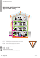
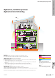
In a lightning protection system set
up on a building, the Type I arrester
achieves the lightning protection
equipotential bonding for the supply
voltage. The Type I arrester is used
when higher pulses are expected and is
installed in the vicinity of the incoming
supply.
The Type I arrester is intended for use
in lightning protection equipotential
bonding, in compliance with DIN VDE
0185 part 1 and IEC 62305. The
Type I arrester meets the requirements
of Type I (B) DIN VDE 0675 and
IEC 61643-1 Type I.
The Type II arrester is used to protect
low-voltage consumer installations and
electronic equipment against surge
voltages arising from atmospheric
discharges (thunderstorms) or
switching operations. The Type II
arresters comply with VDE 0675
part 6, Type II (C), Draft and
DIN VDE 0675 part 6, A2 and the
IEC 61643-11 Type II.
When is a decoupling inductance
needed?
When using Weidmüller arresters of
Type I and II based on varistors, no
decoupling inductance is needed.
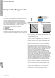
Questions and answers concerning surge protection
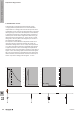
Why are there 3- and 4-pole
versions?
Various arresters are used depending
on the network structure. A widely
used network structure is the
TN system. In the TN-C system, the
electricity supply company routes the
potential of the operational earth of the
low-voltage source (transformer) to the
consumer installation via the integral
PEN conductor. The PE conductor has
the same potential as the N conductor
in this case. A 3-pole arrester is used
here. Every rule has an exception: in the
TN-S system, PE and N are separate.
This means there can be a potential
shift between PE and N. A 4-pole
PU is used in this case. In addition, a
combination of 3- or 4-pole modules
reduces the amount of wiring.
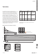
What other network structures are
available?
TT-System
In the TT system, surge protection
Type I/II arresters are not used
between the active conductor and the
earth potential like in TN systems.
Instead they are used between
phases L1, L2 and L3 and the neutral
conductor.
In a “classic“ arrangement of surge
protection devices between the phases
and the earth potential, the devices
may not be capable of extinguishing
mains follow currents at the end of
their lifespan. They could even create a
short circuit. Depending on the earth
resistance that exists for the consumer
installation, a fault current could ow
back to the supply source. Usually,
because of the relatively high loop
resistances in TT systems, the fuses
which conduct the operating current
do not detect this fault current as a
fault and thus do not isolate promptly.
This can lead to increases in potential
in the building‘s entire equipotential
bonding system. Dangerous parasitic
voltages can be transferred if more
distant buildings are being supplied
from these consumer systems or if
consumer loads are being operated via
portable cables beyond the range of
the building‘s equipotential bonding
system. The 3+1 circuitry can be used
in such instances.
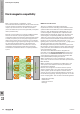
IT-System
An IT system is set up in some
consumer installations for reasons
of availability. A single-phase earth
fault practically creates a TN system.
The power supply is not interrupted
but instead maintained. IT systems
are used in medical applications, for
example. A device for monitoring
insulation provides information on
the quality of the insulation of active
conductors and connected consumers
in relation to the earth potential. Surge
protection devices are incorporated
between the active conductors and the
main equipotential bonding. The fuses,
conductor cross-section and conductor
routes are handled as for T systems.
Likewise, all active conductors are
protected against local earth potential
in sub-circuit distribution boards.
VPU surge protection devices in
Type III surge protection for end
devices are used (such as VPU III or
VPO DS) to protect sensitive consumer
loads. The arrester must be sized for
the voltage of the phase conductor.
W
The basics of lightning and surge protection
W.34 2028840000