
Brochure/Catalogue


What does this have to do with the
3+1 circuitry?
If Type II arresters are now being led
to a neutral conductor instead of a
local earth in a TT system, then, for an
arrester that has become low ohm, only
the wire resistance of the neutral wire
limits the incipient follow-on current.
Immediately after the fault, this is
isolated from the spur line fuses or from
the main fuses that are carrying the
operating current. A pure short-circuit
current has emerged out of a fault
current that was subject to an earthing
facility and resistor. The connection
between the neutral conductor and
the main equipotential bonding is
established using a spark gap. This
conducts the total surge currents
occurring at the installation site
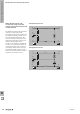
without overloading. This 3+1 circuitry
is also implemented for the circuit
distributors. The phase conductors
L1, L2 and L3 are connected via
the neutral conductor. From there, a
spark gap link is established with the
PE rail. The same information on the
TN system applies when working with
local equipotential bonding systems,
when there is a separate discharge to
the equipotential bonding, and when
the surge protection components are
being arranged ahead of the fault-
current protective circuits.
How does monitoring work with
VPU arresters?
Each individual element of the PU
arrester is equipped with a thermal
monitoring mechanism. This state-of-
the-art design isolates the aged arrester
from the power supply network. This
helps to prevent res. This thermal
monitoring mechanism functions using
a special solder which separates itself
within 30 seconds when a current of
about 0.2 A ows through the varistor.
The functionality is indicated when the
viewing window is green, or for the
Questions and answers concerning surge protection
VPU series with arresters marked R,
using a remote alert output with a CO
contact.
Does a lightning/surge protection
system continue to operate after a
surge voltage?
Yes, if the leakage current on, for
example, the VPU II remains below
the nominal leakage current for each
individual disk. However the varistor
does age during each discharge. The
ageing accumulates over its lifetime
and then leads to the failure of the
arrester after several years. This can
be monitored using remote signalling.
Another method, which is required by
IEC 62305-3, is a periodic check of
the lightning protection system. The
V-TEST can help by allowing you to test
the function of each individual module.
How are the VPU modules tested?
The VPU I, VPU II and VPU III are tested
in accordance with IEC 61643-11.
The arresters from the VPU I series
correspond with Type I and Type II.
The VPU II series corresponds with
Type II and Type III. The VPU III and
VPO DS series are designed and tested
in accordance with the requirements of
IEC 61643-11. They are in Type III.
Where are the VPU modules
installed?
The dimensions of the VPU modules
for installation distributors, comply with
DIN 43 880 A1 draft 6/81.
The Type I arresters are installed in the
vicinity of the power feed and main
equipotential bonding. The Type II
arresters are installed in the distributor
and the VPU III are installed in the sub-
distributions, closer to the object being
protected. The insulation co-ordination
in DIN VDE 0110 requires that facility
components have certain insulation
strengths. This can be achieved
through the gradual application of
arresters in Type I, II and III.
What must be considered when
installing the VPU modules?
IEC 60364-5-53 describes the
selection and installation of surge
protection in buildings worldwide. The
German draft standard VDE V 0100-
534 describes the selection and set-up
of surge protection systems.
What is the difference between a
spark gap and a varistor?
A varistor is a voltage-dependent
resistor which switches off the
surge voltage “softly“. A spark gap
is a mechanical component or an
encapsulated, gas-lled ceramic unit
whereby the spark gap switches
through immediately, and after the
spark, only the ignition voltage is
present (80 – 120 V). Depending on
the type of spark gap, the capability to
suppress the 50-Hz mains follow-on
current must also be considered. The
varistors, however, do not draw any
mains follow-on current.
What are triggered spark gaps?
These spark gaps have additional
electronics. They “see” the interference
pulse and ignite the spark gap. This
means that the protection level is kept
low and the time to spark is reduced.
This saves on decoupling coils.
W
The basics of lightning and surge protection
W.352028840000