
Brochure/Catalogue
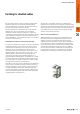


Earthing for shielded cables
Effective shielding
It is important to remember that the shielding should not be
connected to the earth of the module connected, but rather
to the protective earth (PE). In the case of modules
mounted in an earthed, metal housing, the shielding must
be connected to this housing. If an earthed housing is not
available, the shielding must be connected to a separate
earth.
When laying earth connections to shields it must also always
be ensured that no earth loops are formed. The smaller the
earth loop, the lower is the risk of inducing interference
voltages. Therefore, a true star arrangement is the best
answer.
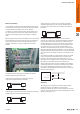
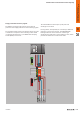
The sketches below show general, feasible connections
between shield and protective earth.
Connecting the shield at one end protects against
capacitive-coupled interference voltages.
System 1System 2
Connecting the shield at both ends is suitable for protecting
against inductive-coupled interference elds.
System 1System 2
A high-resistance connection at one end of the shield is
recommended when trying to avoid the disadvantages of
forming an earth loop in the case of shields connected at
both ends.
System 1System 2
On longer shielded lines, e.g. when a sensor has to be
routed to the control room, the potential difference between
the two ends should not be ignored. If a current-carrying
shield bonding line is used, it is possible to compensate for
the potential difference between the measuring point and
the control room by means of this shield. However, such
shield lines are relatively expensive and also complicated to
fabricate and install. Another possibility is to lay an additional
equipotential bonding line between the measuring point and
the control room. The shield can then be connected at both
ends.
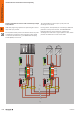
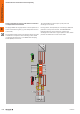
Yet another possibility is a high-resistance earth. The shield
is then connected to earth potential in the control room,
and at the measuring point connected to earth via a gas
discharge tube in a high-resistance arrangement. This solves
the problems of potential transfer and a 50 Hz hum.
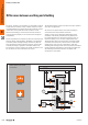
Two gas discharge tubes must be installed for non-oating
measuring points. One connects the shield to earth and the
other to the non-oating measuring point. This prevents
conductive coupling between the measuring circuit and the
earthed measuring point.
Shield connector
Earth
Measuring point
1 4
5
TS
23
IN
OUT
Summary
The earthing is an important factor affecting the reliable
operation of electrical installations in the event of
interference effects. RF aspects must be taken into account.
Only the correct use of materials and well-thought-out circuit
design can bring success.
B
B.1232028840000
Lightning and surge protection
for control and instrumentation signals