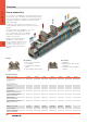
Terminals, W-Series Overview Screw connection For a long time now, Weidmüller's screw mains terminals in the W-series have set the standard for functional perfection down to the very last detail. The combination of many advantages today remains unsurpassed and gives the W-series a unique lead on the market. The W-series offers solutions for conductor cross-sections from 0.08 to 240 mm2 and for all common electrical functions.
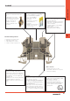
The connection Cross-connections, also pluggable Separation of electrical and mechanical function: • Clamping unit (tension clamp and clamping screw) of hardened steel for very high contact force • Busbar of copper for low voltage loss. Tin-plated surface for minimum contact resistances • Screw-in or pluggable cross-connections • For screw terminals, the pluggable cross-connection (ZQV) is unique, with considerable time savings • Standard cross-connections for 2.
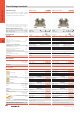
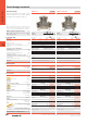
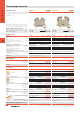
Terminals, W-Series Feed-through terminals 1.5 mm2 2.5 mm2 Standard design WDU 1.5/ZZ WDU 2.5/1.5/ZR Identical external profile for the 2.5mm2 - 10mm2 terminals enables the use of common endplates and partitions thus reducing stocking costs. Additional connection right and left Additional connection right 5.1 x 60 x 47 23 / 2.5 0.13 ... 2.5 5.1 x 60 x 47 32 / 4 0.13 ...
2.5 mm2 WDU 2.5 5.1 x 60 x 47 32 / 4 0.13 ... 4 T IEC 60947-7-1 EEx e II IEC 800 UL 600 T II 2 G D CSA 600 EN 50019 550 2.5 mm2 WDK 2.5 ZQV 2.5 mm2 WDK 2.5 Pluggable cross-connection Screwable cross-connection 5.1 x 65.4 x 63 32 / 4 0.13 ... 4 5.1 x 69 x 63 32 / 4 0.13 ... 4 T IEC 60947-7-1 IEC 60947-7-1 IEC 400 UL 300 CSA 300 EN 50019 EEx e II IEC 400 UL 300 CSA 300 T II 2 G D EN 50019 275 24 25 20 21 24 20 25 24 20 10 21 2.5 AWG 22 …12 AWG 26…12 2.5 2.
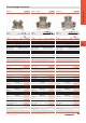
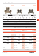
Terminals, W-Series Feed-through terminals 2.5 mm2 2.5 mm2 Standard design WDK 2.5 V WDK 2.5 DU-PE Identical external profile for the 2.5mm2 - 10mm2 terminals enables the use of common endplates and partitions thus reducing stocking costs. Both levels on one potential Lower level earthed on mounting rail 5.1 x 69 x 63 32 / 4 0.13 ... 4 5.1 x 69 x 63 32 / 4 0.13 ...
2.5 mm2 WDK 2.5 EX 4 mm2 WDU 4 6 mm2 WDU 6 Rated voltage 800V 6.1 x 69 x 63 32 / 4 0.13 ... 4 IEC 60947-7-1 IEC 800 6.1 x 60 x 47 41 / 6 0.13 ... 6 7.9 x 60 x 47 57 / 10 0.33 ... 10 T IEC 60947-7-1 UL CSA EN 50019 EEx e II IEC 800 UL 600 T II 2 G D T IEC 60947-7-1 CSA 600 EN 50019 750 IEC 800 EEx e II UL 600 T II 2 G D CSA 600 EN 50019 550 24 32 35 35 28 41 50 45 36 2.
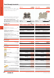
Terminals, W-Series Feed-through terminals Standard design 10 mm2 WDU 10 10 mm2 WDU 10/ZR Supplementary connection, right (4mm2) Identical external profile for the 2.5mm2 - 10mm2 terminals enables the use of common endplates and partitions thus reducing stocking costs. When using ATEX certified components in hazardous area applications the installation instructions and the rated data for accessories in the technical appendix must be considered. Width/Length/Height with TS35x7.5 Max. current / max.
16 mm2 WDU 16 35 mm2 WDU 35 35 mm2 WDU 35 IK With spigot for higher interconnection-stability Clamping screw / spigot (intercon.-stability) Hex. socket screw / spigot (intercon.-stab.) 11.9 x 60 x 63 101 / 25 0.82 ... 25 16 x 60 x 63 150 / 50 2.5 ... 50 16 x 60 x 63 150 / 50 2.5 ...
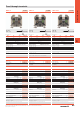
Terminals, W-Series Feed-through terminals 2.5 mm2 2.5 mm2 Compact design WDU 2.5N WDU 2.5N/ZQV The compact design of these protective conductor terminals makes them the obvious choice in confined spaces. With screwable cross-connection With pluggable cross-connection 5.1 x 44 x 37.5 32 / 4 0.13 ... 4 5.1 x 44 x 37.5 32 / 4 0.13 ...
Terminals, W-Series Feed-through terminals 16 mm2 35 mm2 Compact design WDU 16N WDU 35N The compact design of these protective conductor terminals makes them the obvious choice in confined spaces. Suitable for power distribution Suitable for power distribution 12 x 60 x 47 101 / 25 1.5 ... 25 16 x 66 x 51 150 / 50 2.5 ...
Terminals, W-Series PE terminals 1.5 mm2 2.5 mm2 Standard design WPE 1.5/ZZ WPE 2.5/1.5/ZR Identical external profile for the 2.5mm2 - 10mm2 terminals enables the use of common endplates and partitions thus reducing stocking costs. Supplementary connection left and right Supplementary connection, right (1.5mm2) 5.1 x 60 x 47 / 2.5 0.13 ... 2.5 5.1 x 60 x 47 /4 0.13 ...
WPE 2.5 5.1 x 60 x 47 /4 0.13 ... 4 WDK 2.5 PE 2.5 mm2 PE 5.1 x 69.5 x 63 /4 0.13 ... 4 PE T IEC 60947-7-2 IEC 2.5 2.5 mm2 EEx e II UL AWG 22 …12 CSA AWG 26…12 T II 2 G D EN 50019 2.5 T IEC 60947-7-2 IEC 2.5 EEx e II UL AWG 22 …12 800 CSA AWG 26…12 T II 2 G D EN 50019 2.5 400 8 6 300 A (2.5 mm2) 300 A (2.5 mm2) 3 3 A3 / V-0 A3 / V-0 ar#u;~ix? Rated connection KEMA 98ATEX1683 U Additional connection D a# Rated connection KEMA 98ATEX1687 U Additional connection 0.5…4 / 1.
Terminals, W-Series PE terminals Standard design 4 mm2 WPE 4 6 mm2 WPE 6 Identical external profile for the 2.5mm2 - 10mm2 terminals enables the use of common endplates and partitions thus reducing stocking costs. When using ATEX certified components in hazardous area applications the installation instructions and the rated data for accessories in the technical appendix must be considered. Width/Length/Height with TS35x7.5 Max. current / max. cond. cross-section Max.
PE terminals 10 mm2 WPE 10/ZR Terminals, W-Series 10 mm2 WPE 10 Additional connection, right 4mm2 9.9 x 60 x 47 / 16 1.31 ... 16 PE T IEC 60947-7-2 IEC 10 9.9 x 70 x 49.5 / 16 1.31 ...
Terminals, W-Series PE terminals Standard design 16 mm2 WPE 16 35 mm2 WPE 35 Identical external profile for the 2.5mm2 - 10mm2 terminals enables the use of common endplates and partitions thus reducing stocking costs. When using ATEX certified components in hazardous area applications the installation instructions and the rated data for accessories in the technical appendix must be considered. Width/Length/Height with TS35x7.5 Max. current / max. cond. cross-section Max.
Terminals, W-Series PE terminals Compact design WPE 2.5N 2.5 mm2 WDK 2.5N PE 2.5 mm2 PE 5.1 x 60.7 x 62.5 /4 0.13 ... 4 PE The compact design of these protective conductor terminals makes them the obvious choice in confined spaces. When using ATEX certified components in hazardous area applications the installation instructions and the rated data for accessories in the technical appendix must be considered. Width/Length/Height with TS35x7.5 Max. current / max. cond. cross-section Max.
Terminals, W-Series PE terminals Compact design 16 mm2 WPE 16N 35 mm2 WPE 35N The compact design of these protective conductor terminals makes them the obvious choice in confined spaces. When using ATEX certified components in hazardous area applications the installation instructions and the rated data for accessories in the technical appendix must be considered. Width/Length/Height with TS35x7.5 Max. current / max. cond. cross-section Max.
Terminals, W-Series Disconnect terminals 2.5 mm2 Disconnect terminals WTR 2.5 With disconnect terminals the current can quickly and safely be cut to carry our essential maintenance. With clamping screw With socket 5.1 x 60 x 49 14 / 4 0.13 ... 4 5.1 x 60 x 49 14 / 4 0.13 ... 4 2.5 mm2 WTR 2.5 StB When using ATEX certified components in hazardous area applications the installation instructions and the rated data for accessories in the technical appendix must be considered.
Terminals, W-Series Fuse terminals Fuse terminals 2.5 mm2 WTR 2.5/SI 4 mm2 WTR 4/SI When using ATEX certified components in hazardous area applications the installation instructions and the rated data for accessories in the technical appendix must be considered. Width/Length/Height with TS35x7.5 Max. current / max. cond. cross-section Max.
4 mm2 KDKS 1/35 DB 6 mm2 WSI 6 6 mm2 WSI 6 LD Metric fuses 5x20mm Metric fuses Metric fuses / bipolar LED 8 x 73.5 x 55.6 6.3 / 4 0.33 ... 4 7.9 x 60 x 62 6.3 / 10 0.5 ... 10 7.9 x 60 x 72 6.3 / 10 0.5 ... 10 IEC 60947-7-3 / VDE 0611-6 IEC 500 IEC 60947-7-3 / VDE 0611-6 UL 300 CSA EN 50019 IEC 500 IEC 60947-7-3 / VDE 0611-6 UL 300 CSA 300 EN 50019 IEC 500 UL 300 CSA 300 6.3 10 6.3 6.3 6.3 6.3 6.3 6.
Terminals, W-Series Installation terminals Neutral disconnect terminals 2.5 mm2 WNT 2.5 4 mm2 WNT 4 These special terminals for insulation measurements without dismantling of the conductor according to VDE-Norms are prescribed for places of public meetings. When using ATEX certified components in hazardous area applications the installation instructions and the rated data for accessories in the technical appendix must be considered. Width/Length/Height with TS35x7.5 Max. current / max. cond.
Installation terminals 7.9 x 60 x 47 57 / 10 0.5 ... 10 9.9 x 60 x 47 76 / 16 1.31 ... 16 NT IEC 60947-7-1 / VDE 0611-4 IEC UL 400 600 10 mm2 WNT 10 CSA 600 EN 50019 NT IEC 60947-7-1 / VDE 0611-4 IEC UL 400 600 CSA 600 EN 50019 41 45 45 57 60 65 6 AWG 20 …8 AWG 20…8 10 AWG 16 …6 AWG 16…6 6 / 3 6 / 3 A5 / V-0 B6 / V-0 D ar#u;~ix? ar#u;~ix? Rated connection Rated connection 0.5…10 / 1.5…10 1.5…16 / 1.5…16 0.5…10 / 0.5…6 1.5…16 / 1.5…16 12 / 4.0 x 0.8 0.8…1.2 Nm (M 3.
Terminals, W-Series Accessories Supplementary functions Visual separation Side covers Page D.70 Weidmüller offers the user of W-series terminals an extensive range of accessories for the ideal solution to all possible tasks, even over and beyond standard functions. The accessories meet the same quality standards as the actual terminals. To guarantee finger-safe use of terminals, open sides are covered with end plates and partition plates to prevent any contact with live parts.
Fastening Electrical supply Page F.30 Electrical distribution Page D.72 An end bracket is fitted to the right and left of the terminals to locate the terminals on the mounting rail. The marking surface of the end bracket can also be used for group marking. Please turn to Section F for the wide range of Weidmüller end brackets and mounting rails.
Terminals, W-Series Accessories – Visual separation / side covers End plates Shock protection Apart from only a few exceptions, the last terminal of a terminal strip must be covered with an end plate type WAP/AP. End plates are also to be inserted in a terminal strip with different sized terminals. This guarantees protection from live parts and ensures that the terminals are finger-safe (DIN VDE 0106-100).
Accessories – Visual separation / side covers Type 1.5 mm thick Colour WAP WDU 2.5N/4N dark beige WAP WDU 2.5N/4N BL blue WAP WDU 2.5N/4N GE WAP WDU 2.5N/4N OR Qty. Partition plates Order No. for terminal: 50 1060000000 WDU 2.5N 50 1060080000 WDU 4N yellow orange 50 50 1060090000 1060060000 dark beige blue 20 20 1084000000 1084080000 Terminals, W-Series End plate for compact design 1.5 mm thick WAP WDK 2.5/4N WAP WDK 2.5/4N BL WDK 2.5N WDK 2.5N V WDK 2.5N DU-PE WDK 2.
Terminals, W-Series Accessories – Electrical distribution Pluggable cross-connection ZQV In one cross-connection channel adjacent single skipping Unique for screw terminals D Weidmüller is the only producer to offer a pluggable cross-connection system for screw terminals. The pluggable crossconnections stand out with their easy handling and quick assembly, resulting in considerable time savings compared to screwed assembly solutions.
Zubehör - Potenzialverteilung Accessories – Electrical distribution ZQV 2,5N Terminals, W-Series ZQV pluggable cross-connector No. of poles Continuous cross-connector ZQV 2.5N/50 (50-pole) and ZQV 4N/41 (41-pole) are ideal for shortening (e.g. with tool KT ZQV-9002170000) to produce customised configurations with the required number of poles. More than 25 poles in a row are not recommended because of the resulting tolerances in the terminals. Type Qty 2 3 4 5 6 7 ZQV 2.5N/2 60 Order no.
Terminals, W-Series Accessories – Electrical distribution WQV screw cross-connector Any number of poles (extending) Routing 2 potentials in parallel Pre-fitted cross-connectors can be set one after the other to produce any required number of poles. • In spite of only having 1 channel, the WQV cross-connection system can still be used for offset cross-connections. See the photo “parallel skipping”. To do so, arrange the last and first contact points of two identical WQVs so that they overlap.
Accessories – Electrical distribution Terminals, W-Series Screw-in cross-connector – possible combinations In one cross-connection channel adjacent single skipping D extending parallel skipping Possible cross-connections of terminals of the same type with appropriate cross-connectors Terminal type Cross-connection single adjacent skipping Standard parallel extending skipping WDU 1.5/ZZ WQV 2.5 • • • • • WDU 1.5/BLZ WQV 2.5 • • • • • WDU 2.5/1.5/ZR WQV 2.
Terminals, W-Series Accessories – Electrical distribution Screw-in cross-connectors WQV 2.5 Technical data Continuous current 2-pole/multi-pole Thread size Tightening torque A Nm Order data D WQV 4 WQV 6 32 / 32 41 / 41 57 / 57 M 2.5 0.4 ... 0.7 M3 0.5 ... 0.8 M3 0.5 ... 0.8 Order No. Type Order No. Type 2-pole 3-pole 4-pole 5-pole 6-pole 7-pole Type WQV 2.5/2 WQV 2.
Accessories – Electrical distribution WQV 16 WQV 16N WQV 35 76 / 63 101 / 76 76 / 57 138 / 112 M3 0.5 ... 0.8 M4 1.2 ... 1.8 M4 1.2 ... 1.8 M4 1.2 ... 1.8 Type Qty Qty Qty Terminals, W-Series WQV 10 Order No. Type Order No. Type Order No. Type WQV 10/2 WQV 10/3 50 50 1052560000 1054960000 WQV 16/2 WQV 16/3 50 50 1053260000 1055160000 WQV 16N/2 WQV 16N/3 50 50 1636560000 1636570000 WQV 35/2 WQV 35/3 Qty 50 50 1053060000 1053360000 Order No.
Accessories – Specific functions Energy distribution for machines or in buildings usually consists of 5-conductor systems (TN-S). By contrast, energy supply mains are frequently rated as 4-conductor connection. A PEN bridge is used to split the joint PE and N conductor into 2 separate conductors, transforming the TN-S to a TN-C mains. Standard installation Depending on the terminal type, inside or outside PEN bridges are available for both PE and N conductor terminals from 10 mm2.
Mounting rail systems For TS 15 mounting rail 8 Busbars / mounting rails End holders Polyamide 66, screwable Colour Torque Qty EWK AKA 2.5 EW 15 Beige Beige 0.4 Nm 0.4 Nm 50 50 Order no. 0348660000 0382860000 Polyamide with fibreglass, screwable EW 15/2 Dark beige 0.4 Nm 50 1071900000 Polyamide 66, screwless ZEW 15 Beige - 20 7920340000 Polyamide 66, screwable Colour Torque Qty EWK 2 Beige 1.2 Nm 50 0199360000 EWK 1 TS 32 M4X18 EWK 1 ALT Beige Beige 1.2 Nm 0.
Busbar systems Busbars / mounting rails Busbars F Tension clamps (see page F.24 – F.25) In order to bring together neutral conductors and protective conductors at a central point, it is advantageous to use ZB tension clamps together with 10 x 3 or 6 x 6 busbars. The tension clamps can be pushed onto the busbar and adjusted to the entire wiring in the system. The tension clamp serves as the protective conductor connection and can be supplied with green/yellow insulating caps.