
Datasheet
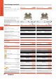
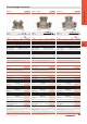
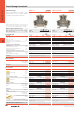
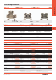
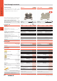
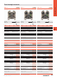


Terminals, W-Series
D.3
D
In detail
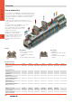
The connection
Separation of electrical and mechanical func-
tion:
• Clamping unit (tension clamp
and clamping screw) of hardened
steel for very high contact force
• Busbar of copper for low
voltage loss. Tin-plated
surface for minimum contact
resistances
Cross-connections, also pluggable
• Screw-in or pluggable cross-connections
• For screw terminals, the pluggable
cross-connection (ZQV) is
unique, with considerable
time savings
• Standard cross-connections
for 2.5 and 4 mm
2
for
up 10 poles
• Pluggable cross-connections
available for up to 50 poles
for own assembly
Simple to use
• Snap on and off at right angles to the mount-
ing rail in both directions
• Integrated idle point when loosening the ter-
minal screws – specially important for me-
chanical screwdrivers
• Screwdriver guided by countersinking of
clamping screws
• All parts captive in the terminal
• Many different options for labelling
Standards
The high contact safety and reliability of Weid-
müller’s systems is verified by:
• Type-testing to IEC 60947-7-1/-2
• National and international approvals
• Large portfolio with UL and CSA approvals
• W-series qualified to railway standards
• ATEX approval
Same contours
• Identical size from 2.5 to 10 mm
• Small number of different accessory parts
• Easier project planning
Wemid insulating material
• Resistant to creep current CTI 600
• Temperature resistant to 120°C
• Combustibility class V0 to UL94
• Contains no halogen or phosphorous
T
Safe contacts
• Elastic tension clamp compensates for
changes in the conductors caused by fluctua-
tions in temperature (prevents working loose)
• No maintenance: no need to retighten the
clamping screw
• Vibration-proof connection: many W-terminals
certified for railway use to EN 61373
• Highest contact force of all connection sys-
tems
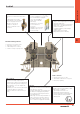
Safe use
• Shock protection with connected conductors,
even with cross-connection
• Terminals supplied with open clamping point.
In addition, the misplugging safeguard pre-
vents conductors from being inserted incor-
rectly (detailed photo).
• Embossing on tension clamp and busbar en-
gage so that even the smallest conductors
are reliably clamped; large conductors and
also 2 conductors are gripped in the middle.