
Datasheet


Busbars /
mounting rails
F.22
F
Articles with coloured order number are kept permanently in stock at the central warehouse in Germany.
Delivery times see page X.2
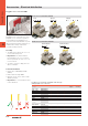
Busbar systems
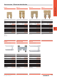
Type Material Cross-section Length Current carrying capacity Qty Order no.
SSch 10x3 Copper, tin-plated 10 x 3 mm 1 m 140 A 1 0348900000
SSch 10x3 Steel, galvanised 10 x 3 mm 1 m 1 0438000000
SSch 10x3 Brass, bright 10 x 3 mm 1 m 100 A 1 0259800000
SSch 6x6 Copper, tin-plated 6 x 6 mm 1 m 140 A 1 0571300000
SSch 6x6 Brass, bright 6 x 6 mm 1 m 100 A 1 0571200000
SSch 15x6 Copper, tin-plated 15 x 6 mm 1 m 265 A 1 0357400000
Busbars, unperforated SSch
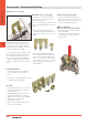
Type Material Cross-section Length Power Rating Qty Order no.
NSch 15x2 Copper, bright 15 x 2 mm 1 m 80 A 1 0280200000
ESch 12x2 Steel, galvanised 12 x 2 mm 1 m 1 0280300000
Pressure piece Qty Order no.
DKSUE 100 0280100000
Clamping screw Qty Order no.
BFSC M5x8 100 0296700000
Busbars, perforated NSch / ESch
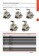
In switchgears and controls, it may be necessary
to bring the neutral conductor and the protective
conductor together at a central point. Busbars are
available for this purpose and can be used for con-
necting a large number of conductors in a con-
fined space (up to 70 conductors on a 1 m bus-
bar). The conductors are connected by means of a
pressure piece or tension clamp; the former does
not entail bending the eyelets. A guide lug on the
pressure piece engages in the busbar and holds
the pressure piece firmly so that it cannot twist.
The tension clamps can be pushed on the busbar
and adjusted to the entire wiring in the system.
The busbars can be used unperforated in any
lengths. They are fixed using the SH busbar holder
which can, for longer busbars, also be positioned
between the tension clamps.
Connection data NSch/ESch
Screw connection solid 0.5 ... 2.5 mm
2
Stripping length 9 mm
Cable lug connection max. 16 mm
2
Max. current per connection 27 A
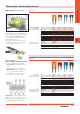
Busbars Tension clamps (see page F.24 – F.25)
In order to bring together neutral conductors and
protective conductors at a central point, it is ad-
vantageous to use ZB tension clamps together
with 10 x 3 or 6 x 6 busbars. The tension clamps
can be pushed onto the busbar and adjusted to
the entire wiring in the system.
The tension clamp serves as the protective con-
ductor connection and can be supplied with
green/yellow insulating caps. These caps indicate
the protective function and marking tags allow
clear identification of each conductor.
If the tension clamps are used to connect neutral
conductors, they can be marked with a blue insu-
lating cap.
ZBE6 can also be swivelled onto the busbar retro-
spectively.