de Bedienungsanleitung Zähler und Totaliser mit Zusatzfunktionen und Grenzwertüberwachung 3 en Operating instructions Counter and totaliser with auxiliary functions and threshold monitoring 24 PTX800D 61001050/00/01.
en PTX800D Contents Operation 25 Setup options 27 Setup Sequence 31 Installation 34 Modifications 39 Output calibration 40 24
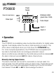
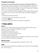
en PTX800D PTX800D Power for Input device Pulse Input Power Supply Total or Rate Display Analogue output (gives rate or total) Pulse Output Alarm 1 Reset Pulse Input Alarm 2 • Operation General The PTX800D is a scalable pulse counter/rate indicator for digital pulse signals. It will display either the rate or total according to setup. The other value is displayed when you hold down the TOTAL/RATE key.
Viewing the alarm setpoints Press the AL1 or AL2 at any time to display the setpoint for that channel. The value will be shown for 5 s. If the alarms are disabled, pressing the key will have no effect. Changing the alarm setpoints Press PGM while the setpoint is on display (see above), you will be able to change the value using the ì and Å keys. To save the changes, press PGM. Note: you can disable this feature during setup for greater security.
Changing the setup options You should only use setup mode if you have to change a setting or calibrate the outputs. The setup mode stops all operation. As soon as you have setup the last parameter, the unit behaves as if it has been switched on with the new settings. This does not mean that the total is reset - you must do this yourself if necessary. If you want to abandon all the changes you have made, simply remove the security link (or remove the power) before the save message is shown.
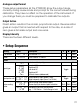
Input signal type Sets the input trigger and reset levels to suit the pulse source. The table below gives the threshold values. For contact closure inputs, the software incorporates debouncing (minimum pulse width 20 mS / maximum frequency 10 Hz). Low voltage inputs High voltage inputs Trigger Reset Trigger Reset LOAC 50 mV -50 mV 200 mV -400 mV Low level AC signals HIAC 2.5 V -2.5 V 14 V -10 V High level AC signals LOdC 3.5 V 0.
Rate scaling factor The rate scaling factor sets the ratio between the total display and the rate display. It must be a power of ten (i.e., 1000, 100, ..., 0.01, or 0.001). Number of samples The PTX800D calculates the rate every 260 mS. The analogue output and display are then updated from the average over the programmed number of samples. For example, if you set the number of samples to 10, the analogue output and rate display will be updated every 2.6 s.
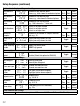
Alarm action High alarms are active above the setpoint and low alarms are active below the setpoint. Total alarms are always ‘high’ type, so this setting is not shown. Deadband This parameter sets the “hysteresis” for an alarm channel; the alarm will clear above or below the setpoint to prevent chatter when the rate level passes the setpoint. The minimum deadband is one display count. Total alarms do not need a deadband setting.
Analogue output format These setup parameters let the PTX800D show the output range correctly during review mode and prompt for the correct values during calibration. They have no affect on the operation of the instrument. If you change them you must be prepared to calibrate the outputs. Output Action Direct action results in the normal, proportional output. Reverse action gives an output that is inverted with respect to the rate, so a rate of zero gives a full scale output and vice versa.
Setup Sequence (continued) Total and rate display settings and scaling Total decimal tot_dp= Introduces total decimal point Demo, e.g., total shown to one decimal place point 1234.5 tot_dp= 12.
Setup Sequence (continued) General alarm settings Setpoint SECure_y Setpoints fixed at setup security SECure_n Can change setpoints Alarm reset reS_Auto Automatic reset sequence rES_Oper Manual reset Analogue output settings (not shown unless outputs are fitted) Rate or total Out=rate Analogue output proportional to rate output Out=_tot Analogue output proportional to total Rate range represented Total range represented Output type Output range Output Action rate_LO= 0.00 rate_HI= 100.00 tot_LO= 0.
Installation Caution: In order to meet product safety requirements, these units must only be installed, by qualified staff, in accordance with the information given in this manual, using the mounting clips and terminal blocks supplied, and all relevant national electrical wiring and safety rules must be followed. Locate the instrument in an area that is free from dust, moisture and corrosive gases (pollution degree II or better). Do not cover the ventilation holes at the side of the case.
Input voltages over 45 V DC If the input voltage is above 45 V DC connect the internal high voltage select jumper before applying the signal (maximum voltage is 250 V DC). Digital pulse output The basic model PTX800D has a retransmit pulse output, which gives a single pulse every time the total increases by one unit. The pulse width is a constant 32 ms and the minimum off time is 32 ms.
Connections For effective protection from electromagnetic noise, all signal cables must be shielded, or located on conductive trays or in conduits. Strip wires to 7 mm from the ends. Use a suitable ferrule for multistranded wires (do not solder).
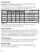
Symbols The instrument labels use symbols in accordance with IEC61010-1: - Consult documentation; Insulated. - Direct Current; - Double Link both pairs of posts for voltage outputs PTX800 analogue output board showing output type jumper locations.
38 – Sig Sensor + Sig + Sensor – NAMUR sensor For externa y powered PNP open co ector sensor nputs For externa y powered NPN open co ector sensor nputs For NAMUR sensor nputs. 9 10 11 12 PTX800D 9 10 11 12 PTX800D 9 10 11 12 PTX800D + Power (–ve) Signal – Sig Power (–ve) LOAC HIAC LOdC HIdC CoN Signal For 3-w re sensors w th PNP open co ector outputs 9 10 11 12 PTX800D 9 10 11 12 PTX800D -50 m -2.5 V 0.5 V 3V 3V 2.5 V 3.
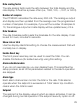
• Modifications Analogue output type The analogue output type (current/voltage) is set by internal push fit jumper. To change the output type: Change the output type push fit jumper: 1. Gently remove the backplate (it is held in place by four lugs). 2. Slide the electronics from the housing. 3. Change the jumper location to the required setting (see diagram above). 4. Look inside the housing and note that there are connectors that mate with the display board. 5.
High/Low voltage input selection 1. Gently remove the backplate (it is held in place by four lugs). 2. Slide the electronics from the housing. 3. Change the High/Low voltage jumper to the required setting (see diagram right). 4. Look inside the housing and note that there are connectors that mate with the display board. 5. S lide the electronics gently back into the case. Carefully moving the board until the keypad connectors engage with the display board. 6. Replace the backplate.
Procedure Note: the procedure below shows calibration for the commonly used 4‑20 mA format. If you have set the outputs to any other format, the unit will prompt you with the output high and low values you have chosen. When the display shows Action/Description Put the instrument in setup mode and scroll through the main menu CALOut_n Press ì or Å CAlOut_y Press PGM to select output calibration Out_LO_= Connect the multimeter to measure the output level, then press PGM Press PGM 4.
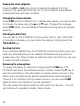
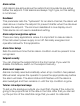
Analogue Output Board Display Board Link these pins for Normal input voltages Link these pins for High input voltages Main Board Dimensions 137 00 mm 96 6 mm PGM EN PANEL THICKNESS Max 18 0mm AL2 TOTAL RATE T CUTOUT 60.0 mm Front panel is rated IP65 when correctly Installed in panel 15 5 mm 96.6 mm 42 AL1 92 0 mm (+0 8 / 0 0 mm) 5.5 mm GASKET 18 0 mm Temperature range: 0-60 °C Altitude: < 2000 m Relative humidity: 0-95 % (non-condensing) 45.0 mm (+0.6 / -0.0 mm) 48.8 mm 44.
43
Weidmüller Interface GmbH & Co. KG Postfach 3030 32720 Detmold Klingenbergstraße 16 32758 Detmold Tel. +49 5231 14-0 Fax +49 5231 14-20 83 info@weidmueller.com www.weidmueller.com 61001050/00/01.