User Manual WI-I/O 9-K Wireless I/O For WI-I/O 9-1,2,3,4, products, refer to separate User Manuals Weidmuller, Inc., Richmond, VA 23236 Tel: (800) 849-9343 Fax: (804) 897-4134 Web: www.weidmuller.
WI-I/O 9-K v1.9 Thank you for your selection of the WI-I/O 9-K product. We trust it will give you many years of valuable service. ATTENTION! Incorrect termination of supply wires may cause internal damage and will void warranty. To ensure this product enjoys a long life, double check ALL your connections with the user’s manual before turning the power on. CAUTION: This device should not be operated within 8 inches (20cm) of people, in accordance with CFR 47 Section 1.
User Manual v1.9 FCC Notice: WI-I/O 9-K Wireless Module This Users Manual is for the WI-I/O 9-K wireless module. This device complies with Part 15.247 of the FCC Rules. Operation is subject to the following two conditions: 1) This device may not cause harmful interference and 2) This device must accept any interference received, including interference that may cause undesired operation. This device must be operated as supplied by Weidmuller, Inc.
WI-I/O 9-K v1.9 Important Notice Weidmuller, Inc. products are designed to be used in industrial environments, by experienced industrial engineering personnel with adequate knowledge of safety design considerations. Weidmuller, Inc. radio products are used on unprotected license-free radio bands with radio noise and interference.
User Manual v1.9 Limited Warranty, Disclaimer and Limitation of Remedies Weidmuller, Inc. products are warranted to be free from manufacturing defects for the “serviceable lifetime” of the product. The “serviceable lifetime” is limited to the availability of electronic components. If the serviceable life is reached in less than three years following the original purchase from Weidmuller, Inc., Weidmuller, Inc. will replace the product with an equivalent product if an equivalent product is available.
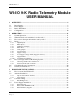
WI-I/O 9-K v1.9 WI-I/O 9-K Radio Telemetry Module USER MANUAL 1 OVERVIEW ----------------------------------------------------------------------------------------- 8 1.1 Input Signals ................................................................................................................. 8 1.2 Power Supply................................................................................................................ 9 1.3 Radio Transmitter ...........................................................
User Manual v1.9 3.5 3.5.1 3.5.2 3.5.3 3.5.4 Input Signal Connections............................................................................................ 31 Digital/Pulse Inputs......................................................................................................... 31 Shaft Encoder Connections............................................................................................. 31 Analog Input.................................................................................
WI-I/O 9-K v1.9 1 OVERVIEW Note: Please refer to separate User Manuals for the WI-I/O 9-1,2,3,4 products. The WI-I/O 9-K product will be referred to as the “WI-I/O K” for the rest of this manual to clearly delineate it from the other WI-I/O 9-1,2,3,4 products. The WI-I/O K radio telemetry module is an economical solution for the remote monitoring of process signals. The WI-I/O K can connect to digital, pulse or analog signals from process transducers, and transmit these signal values by radio.
User Manual v1.
WI-I/O 9-K v1.9 be configured for each input-to-output link. The configuration is done at the WI-I/O K module where the input signal is - no additional configuration is required at the WI-I/O 9-x modules. The transmitted radio message will include the address of repeater modules - modules with these addresses will re-transmit the messages. 1.4 Configuration Each module must be configured before it can be used.
User Manual v1.9 2 OPERATION 2.1 Normal Operation Once configured using the WI-I/O K configuration software, the WI-I/O K module will normally be in “sleep” mode to conserve power. During sleep mode, the microprocessor controller powers down, and the analog loop supply is turned off. The microprocessor will automatically “wake up” and revert to full operation if a digital/pulse input changes (on to off, or off to on), or every 0.5 seconds to check if a timed update transmission is due to be sent.
WI-I/O 9-K v1.9 input during the next 30 seconds, regardless of changes to the input signal. Note that paralysis time does not stop re-transmissions of each message - if the WI-I/O K is configured to transmit each message three times, then paralysis will not stop this. Depending on the type of input signal (digital, pulse or analog), the WI-I/O K must determine what type of signal change is required to send a transmission: 2.4 Inputs 2.4.
User Manual v1.9 Each pulse input is counted as two 16 bit registers. The first register is the pulse count, and the second register is the count of “overflows” of the first register - these two registers provide a 32 bit count of the pulse input. Each register can be transmitted individually. A “sensitivity” value is configured for each pulse input (0 - 32 000). Whenever the pulse count has increased by this value since the last transmission, the WI-I/O K will transmit the new pulse count.
WI-I/O 9-K v1.9 Overview: • Pulse inputs are counted as 2 x 16 bit registers. • Pulse count is transmitted when the count has increased by the sensitivity amount since the last transmission. • Update message if the input value has not been transmitted within the update time (10 seconds - 7 days). • After each transmission, another transmission for that input is disabled for the paralysis time (0 – 127.5 sec). • PI2 can be scaled by a configurable divider.
User Manual v1.9 50% if the level is decreasing. If an incremental shaft encoder is used, then the rate may be scaled by scaling PRATE1. If a quadrature encoder is used, scale PRATE2. The scaling value will determine both the 100% analog signal (e.g. 20mA) and 0% signal (e.g. 4mA). For example, if a maximum pulse rate of 10Hz is configured, then the analog signal will be: 100% if the encoder increases at 10Hz 50% if the encoder pulse rate is 0 0% if the encoder decreases at 10Hz.
WI-I/O 9-K v1.9 When the WI-I/O K takes a measurement, it will transmit the analog value if the value has changed by more than the pre-configured sensitivity since the last transmission. The sensitivity can be configured from 0.1% to 75% with a default value of 3%. If the change in the signal since the last transmitted value is less than the sensitivity, then the WI-I/O K will not transmit the analog value. The sensitivity value should be selected which is more than the normal analog signal noise.
User Manual v1.9 • Analog value is transmitted if the measured value has increased by the configured sensitivity amount since the last transmission • Analog value is transmitted if the input value has not been transmitted within the update time (10 seconds – 7 days) • There is no paralysis time for the analog input. 2.4.6 Setpoint Status The setpoint status is an internal status value, calculated by comparing the analog input to two configurable setpoint values.
WI-I/O 9-K v1.9 This indication is however available at the receiving WI-I/O 9-x by using the WI-I/O 9-x Output Reset on Comms Fail function. To use this function, map an input that is not being used on the WI-I/O K to a spare output on the WI-I/O 9-x. The unused input can be an internal input such as the Low Voltage status or Setpoint status, or even the analog input as this can also be mapped to a digital output.
User Manual v1.9 number of update transmissions per hour. The probability of success for an individual message depends on the transmission density and the number of re-transmissions for each message.
WI-I/O 9-K v1.9 20+km in Australia/NZ (1W RF power permitted). To achieve these distance, at least one site needs to be elevated on a hill or transmission tower - refer section 3.2 for more information). 2.6 Calculating Power Consumption The following information may be used for calculating power consumption. Quiescent Each radio transmission Analog input measurement (per measurement) Voltage Supply ∆ volts (6 – 30) mA WI-BP-I/O-9-K Battery Pack mAHr 0.14 700 300 180 150 10 3.4 per day 0.
User Manual v1.9 Digital input Update time, off state 1 day Update time, on state 15 minutes Input is expected to be on twice per year for 4 hours No. of change messages per year = 2 (twice per year) * 2 (on to off and off to on) = 4 No. of “off” update messages per year = 364 (approximately) No.
WI-I/O 9-K v1.9 Power for pulse input Average pulse rate is 1 pulse per hour (0.0003Hz), so power required = 0.06 x 0.0003 per day = zero = 3.4 per day * 365 = 1241 mAHr per year Quiescent power Power for quiescent current Total power consumption per year = Expected battery life is 15 + 526 + 0 + 1241 = 1782 mAHr = 1700/1782 = 0.95 year Note that battery life is shortened during configuration or diagnostics.
User Manual v1.9 3 HARDWARE INSTALLATION WARNING! 110/220/240V mains power must NOT be connected to any input terminal of the WI-I/O K module! The WI-I/O K module is housed in a weatherproof enclosure with external power and input signals connected via a weatherproof connector at the bottom of the module. Wires of up to 0.75 sqmm may be connected by soldering to the female connector supplied with the unit. The antenna/coaxial cable connector is a SMA female at the top of the module.
WI-I/O 9-K v1.9 connect to an earthed surface. If this is not possible, use an earth lug in the mounting screw connection and secure the other end of the wire to a good earth. 3.2 Antenna Installation The WI-I/O K module will operate reliably over large distances. The distance which may be reliably achieved will vary with each application - depending on the type and location of antennas, the degree of radio interference, and obstructions (such as hills or trees) to the radio path.
User Manual v1.
WI-I/O 9-K v1.9 Dipole and Collinear antennas. A collinear antenna transmits the same amount of radio power in all directions - as such that are easy to install and use. The dipole antenna with integral 15 ‘ cable does not require any additional coaxial cable, however a cable must be used with the collinear antennas. 1m minimum 3.2.1 Collinear and dipole antennas should be mounted vertically, preferably 1 metre away from a wall or mast to obtain maximum range.
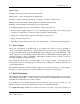
User Manual v1.9 the common (or “central” station should have a dipole or collinear (non-directional) antenna. 3.3 Connection Plug External power and input signals are connected using a 7-pin weatherproof plug, provided with the module. The plug needs to be assembled as per the following diagram. External supply connection is not required when using the WI-BP-I/O-9-K battery pack.
WI-I/O 9-K v1.9 WI-PL1-9-K Plug Lead The WI-PL1-9-K plug lead assembly is a 1 metre (3’) cable pre-terminated to the connector plug. The connector connections are: Red Supply voltage + Blue DIN1 Green DIN2 Yellow Analog loop supply White AIN + Black AIN – Drain wire with sleeve Common 3.4 Power Supply Installation 3.4.1 External Power The WI-I/O K module will accept an external supply of 6 - 30 volts DC. An external supply with a battery and battery charger is suitable.
User Manual v1.9 3.4.2 Battery Pack WI-BP-I/O-9-K The WI-BP-I/O-9-K can be installed underneath the WI-I/O K or beside it. The WI-BP-I/O-9-K uses the same type of enclosure as the WI-I/O K and is mounted in the same way. The WI-BP-I/O-9-K has a “cable tail” which plugs into the WI-I/O K. The input wiring is then connected to a socket on the WI-BP-I/O-9-K. The lid of the WI-BP-I/O-9-K can be rotated to suit installation. A second WI-BP-I/O-9-K can be connected to the first in a similar manner.
WI-I/O 9-K v1.9 is typically 15 to 120 °F (-10 to 50 °C). Special “industrial” batteries, such as Eveready EN91, have a wider temperature range, -20 to 130 °F (-30 to 55 °C). Operation of the WI-I/O K will stop during battery change; however configuration of the module will not be lost when batteries are removed, so no special procedure is required when changing batteries of the same type.
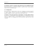
User Manual v1.9 3.5 Input Signal Connections 3.5.1 Digital/Pulse Inputs Digital and pulse inputs share the same input channel. Each input is connected between the DIN connector and COMMON. Inputs can be voltage-free contacts, NPN transistor switches, or a TTL voltage signal (ON < 1.5 volt DC, OFF > 3.5 volts DC). ⊂ DIN1 ⊂DIN2 NPN ⊂ WI-I/O-K GND Inputs can be voltage free contact or open-collector transistor Inputs do not have any surge protection.
WI-I/O 9-K v1.9 ANALOG SUPPLY ⊂ AI+ ⊂ + ⊂ - ⊂ AI- + ⊂ WI-I/O K GND LOOP POWERED TRANSDUCER AI+ WI-I/O K ⊂ AI- - ⊂ GND EXTERNALLY POWERED TRANSDUCER Each input has a loop resistance of 150Ω and zener diode protection against overvoltage and reverse voltage. Voltage Input Voltage inputs are connected to the AI+ and AIconnections. The maximum voltage signal that can be measured is 10V.
User Manual v1.9 connecting to the WI-I/O K module. 3.5.4 RS232 serial port An RS232 port is provided for connection of a PC for configuration and diagnostics. To access the serial port DB9 connector, remove the front cover from the module by unscrewing the four screws in the front panel. The serial port is a 9 pin DB9 male and provides for connection to a terminal or to a PC for configuration, field testing and for factory testing. Communication is via standard RS-232 signals.
WI-I/O 9-K v1.9 4 CONFIGURATION The WI-I/O K module is configured by creating a configuration file on a PC and downloading to the WI-I/O K via the RS232 serial port. You will require the configuration software, and a serial cable - refer to the previous section for details on the cable. The configuration software is supplied as "free-ware" on the Product Catalog CD supplied with each order. The configuration software for the WI-I/O K is the same as the software for the WII/O 9-x. Please read section 4.
User Manual v1.9 4.1 I/O Mapping Enter I/O mappings as per the WI-I/O 9-x manual. In the following example, a digital input at a WI-I/O K is mapped to DO1 of WI-I/O 9-x#3. The analog input of the WI-I/O K is mapped to AO2 of the same module. DIN1 WI-I/O K WI-I/O 9-1 AIN DO1 (DIN1 from #14) AO2 (AIN from #14) #3 #14 DO3 (SP inv from #14) #4 WI-I/O 9-1 AO1 (AIN from #14) The setpoint status of the WI-I/O K is mapped (inverted) to DO3 of WI-I/O 9-x#4, using WI-I/O 9-x#3 as a repeater.
WI-I/O 9-K v1.9 4.2 Update Transmission Times Each input signal has an update time. If a change has not occurred for this input within this time, then a transmission is set for this input after the update time has expired. Each input signal has its own timer - when a transmission occurs for this input (either a change transmission or an update transmission) the timer is reset to zero. If the timer reaches the Update Time value, then a update transmission occurs.
User Manual v1.9 message during the paralysis time - this is to prevent overcrowding of the radio channel. An example could be a system monitoring environmental alarms. Normally there would be few change messages, but under abnormal conditions, a lot of change messages could be generated in a short time period. The paralysis time will allow each module to send the first change message, but subsequent change messages are disabled during the paralysis time.
WI-I/O 9-K v1.9 supply. Consider the above example, with WI-I/O K #14. T his module is mounted on a water tank, and the analog input is a level transducer. The WI-I/O K is powered by a WI-BP-I/O-9-K battery pack and to conserve power, a measurement is taken every 30 minutes (1800 sec). The transducer requires a warmup time of 7 seconds to achieve accuracy, so a value of 10 seconds is chosen.
User Manual v1.9 4.6 Supply Voltage The supply voltage may be mapped as an internal analog input. The 16 bit value corresponds to 0-30V. There is no analog sensitivity for this measurement - it is only transmitted based on the configured update time. The measurement is taken every time the WI-I/O K transmitter operates. The supply voltage also has user-configurable setpoints to determine the Supply Low Volts alarm. These setpoints can be set from the SetPoint option.
WI-I/O 9-K v1.9 4.7 Pulse Inputs Each WI-I/O K has two pulse inputs. Each pulse input has 2 x 16 bit counters and a calculated pulse rate value. The 2 x 16 bit counters are a base counter which increments on each pulse, and an “HI” counter which increments each time the base counter overflows. Either or both counters can be transmitted, although each is transmitted individually. There are several configurable parameters for pulse inputs.
User Manual v1.9 Example 1: A turbine meter is connected to a WI-I/O K with a pulse signal of 15 pulses per gallon. The normal flow rate is 30 gallons/sec - that is, the normal pulse signal is 450Hz (15x30). The flow signal is connected to PI2, and divider of 15 is selected such that the pulse count is scaled to units of gallons. Both PI2 counters are transmitted to a module for interfacing to a HMI package. The HMI will read both counter values and calculate a 32 bit totalized flow value.
WI-I/O 9-K v1.9 Example 2: A system of tipping bucket raingauges is installed to monitor rainfall in a catchment area. Each raingauge provides a pulse signal to a WI-I/O K - each pulse represents 1/100th inch of rain. The user wants a transmission at each pulse.
User Manual v1.9 4.7.1 Manually Setting Counter Values The values in the counters can be manually set to any value - refer to section 5.3.2 of this manual. 4.7.2 Shaft Encoder Inputs If the pulse inputs are connected to a shaft encoder (incremental or quadrature types), then the Shaft Encoder Inputs option should be selected. The WI-I/O K will then look at both pulse input signals and calculate a “position” value for the shaft encoder.
WI-I/O 9-K v1.9 100% value at 50Hz. The maximum pulse rate can be configured from 0.02 Hz to 1000Hz. For shaft encoder inputs, you can use PR1 for incremental encoders and PR2 for quadrature encoders. The rate signal will be 50% for 0 Hz, between 50 – 100% when the encoder is increasing and 0 – 50% when the encoder is decreasing. If you configure the maximum pulse rate to be X Hz, then the analog value will be 100% at X Hz increasing, and 0% value at X Hz decreasing. 4.
User Manual v1.9 Loading Configuration from a Module Care should be taken when loading a configuration from a module. It is easy to lose the system address and unit address. We suggest that you first view the system address and unit address you can do this via the “Unit Options” menu. Note these addresses before loading the configuration. When you upload the configuration, the program will check if you want to load the addresses from the module.
WI-I/O 9-K v1.9 5 DIAGNOSTICS AND TESTING 5.1 System Problems Most problems relate to incorrect configuration, or radio path problems. Before installing the WI-I/O K module, "bench-test" its operation with the receiving WI-I/O 9-x module alongside. If the WI-I/O K does not work properly in this test, it will not work properly installed. If problems are found, check the configuration.
User Manual v1.9 Note : The OK LED will generally not light continuously unless the cable is in place and the configuration software is running. 5.3.1 Read Inputs This option provides a display of the measured input signals in the WI-I/O K, both internal and external. Digital inputs (internal and external) are displayed as "ON" or "OFF", the pulse input accumulated count values are displayed and the analog input value is displayed in mA or V.
WI-I/O 9-K v1.9 below. The counter values will display both base and Hi counters as a 32 bit number, but in “decimal” format. If the counter value is less than 65536, then the Hi or overflow counter is zero. 5.3.2 Setting Counter Values To manually set counter values, highlight the existing counter values and over-type the new value required. Then select the green “3” box beside counter #2. The new values will be written into the module. 5.3.
User Manual v1.9 6. Now adjust the signal to the maximum value (100%). Select “Process High Value”. 7. When you have finished this process, select “Write Configuration” - this will write the configuration values to the user-calibration registers in the WI-I/O K. Select “Done” and the analog signal is calibrated. The accuracy of the analog signal can only be as accurate as the calibration.
WI-I/O 9-K v1.9 6 SPECIFICATIONS General EMC approval FCC Part 15 Radio standards USA FCC Part 15.247 902 – 928 MHz, 1 Watt Canada RSS-210 Housing 160 x 64 x 36mm NEMA 4 (IP66), except for Class 1 Div 2 areas in North America. I/O & Power Connection Weatherproof connector bayonet Suitable for 18 gauge (0.
User Manual v1.
WI-I/O 9-K v1.9 configurable 0.5-100 seconds. Analogue Input Setpoint Configurable high & low setpoint may be transmitted to remote units, allowing set/reset of remote digital outputs System Parameters Network Configurations Max. number of WI-I/O 9-K inputs is >20,000 if WI-I/O 9-C/G modules are used as receivers.
User Manual 7 WARRANTY We are pleased that you have purchased this product. Weidmuller, Inc. products are warranted to be free from manufacturing defects for a period of 2 years from the effective date of purchase. The effective date of purchase is decided solely by Weidmuller, Inc.