Quick Start Guide WI-I/O 9-L-T Wireless I/O Transmitter Unit WI-I/O 9-L-T QuickStart v1.
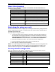
WI-I/O 9-L Transmitter Unit Quick Start Guide This document is the WI-I/O 9-L-T Wireless I/O Transmitter Unit Quick Start Guide and contains the following sections: Section Read this section if you want to … Basic steps for using your unit Learn the basic steps for installing and using your unit. Factory default configuration Understand how the transmitter sends information to the receiver. Unit components Understand the different parts of your unit.
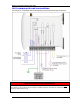
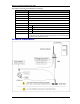
WI-I/O 9-L Transmitter Unit Quick Start Guide Your WI-I/O 9-L-T transmitter unit has the following components and terminal connections: **IMPORTANT ELECTRICAL SAFETY INFORMATION** In order to comply with Electrical Safety Regulations, this module must be installed in an Electrical AND Fire enclosure. This enclosure may be a single or multiple enclosures. Access to the module is to be made by a Service Person only. WI-I/O 9-L Transmitter Unit Quick Start v1.
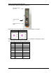
WI-I/O 9-L Transmitter Unit Quick Start Guide The front panel contains the following components: SMA antenna connector at top of unit RS232 configuration port Rotary switch for set-point settings The triangle on the rotary switch indicates the current position, for example: Position 0 Position 1 NOTE: To avoid damaging the rotary switch, use a screwdriver to change the position. The rotary switch uses the following setpoint levels: Position Lower level (mA) Upper level (mA) 1 4.8 6.4 2 6.4 8.
WI-I/O 9-L Transmitter Unit Quick Start Guide The LEDs on the front panel indicate the unit status: LED Status Indicates None No power supply. OK LED Green Current status of the unit OK. OK LED Red Fault condition detected in unit. TX Led Flashes Transmitting Message. PG LED on Configuration Cable Connected. Input LED ON Input LEDS (i.e. D1,D2, SP, AZ.) light when the corresponding input is active. All LEDs medium flash D1 Digital Input 1 is active (Low). D2 Digital Input 2 is active.
WI-I/O 9-L Transmitter Unit Quick Start Guide To reset the default factory configuration: 1. Set the RSSI rotary switch to position 0 using a screwdriver. 2. Power on the WI-I/O 9-L-T transmitter. 3. The WI-I/O 9-L-T transmitter flashes all LEDs at medium flash (i.e. 1.6 Hz). NOTE: If the LEDs do not flash, you must repeat steps 1 and 2 until the LEDs flash before continuing. 4. Set the RSSI rotary switch to another position (i.e. position 1) within 5 seconds. 5.
WI-I/O 9-L Transmitter Unit Quick Start Guide Thank you for selecting the WI-I/O 9-L-T transmitter for your telemetry needs. We trust it will give you many years of valuable service. To ensure your WI-I/O 9-L-T transmitter enjoys a long life, double-check ALL your connections with the user’s manual before powering on the unit. WARNING: Incorrect termination of supply wires may cause internal damage and will void warranty. Exposure to RF energy is an important safety consideration.
WI-I/O 9-L Transmitter Unit Quick Start Guide Document information Quick Start Guide WI-I/O 9-L-T Wireless I/O Transmitter Unit Contact details Address > 821 Southlake Blvd., Richmond, VA 23832 Telephone > (800) 849-9343 Fax > (804) 897-4136 Email > info@weidmuller.com Website > www.wireless.weidmuller.com Limited lifetime warranty, disclaimer and limitation of remedies Weidmuller Inc. products are warranted to be free from manufacturing defects for the “serviceable lifetime” of the product.