User Manual WI-I/O 9-L I/O Module Weidmuller Inc., 821 Southlake Blvd., Richmond, VA 23236 Tel: (800) 849-9343 Fax: (804) 897-4136 Email: support@weidmuller.com Web: www.weidmuller.
Thank you for your selection of the WI-I/O 9-L I/O Module. We trust it will give you many years of valuable service. ATTENTION! Incorrect termination of supply wires may cause internal damage and will void warranty. To ensure your WI-I/O 9-L product enjoys a long life, double check ALL your connections with the User Manual before turning the power on. All equipment must be properly grounded for safe operation. All equipment should be serviced only by a qualified technician.
WI-I/O 9-L Configuration Manual What’s in this document....................................................................................................................... 7 Document conventions.................................................................................................................................... 8 Introduction to WI-I/O 9-L .................................................................................................................... 9 Key features ...................
WI-I/O 9-L Configuration Manual Showing and printing the unit summary.................................................................................................... 58 Showing and printing the unit mappings................................................................................................... 59 Deleting units ................................................................................................................................................ 60 Transmitter information..........
WI-I/O 9-L Configuration Manual This page intentionally left blank.
WI-I/O 9-L Configuration Manual Safety information Thank you for selecting the WI-I/O 9-L for your telemetry needs. We trust it will give you many years of valuable service. To ensure your WI-I/O 9-L enjoys a long life, double-check ALL your connections with the Installation Guide before powering on the module. WARNING: Incorrect termination of supply wires may cause internal damage and will void warranty. Exposure to RF energy is an important safety consideration.
WI-I/O 9-L Configuration Manual This document is the WI-I/O 9-L Configuration Manual that describes how to install and use the WI-I/O 9-L. This document contains the following sections: If you want to … Description For more information, see … Understand how WI-I/O 9-L works Explains how WI-I/O 9-L works and provides information about the main features of WI-I/O 9-L. Introduction to WI-I/O 9L on page 9.
WI-I/O 9-L Configuration Manual This document uses different fonts to indicate specific information. Bold indicates a menu option that you can select, or a button/icon that you can click to activate. Double quotes (““) indicate a cross-reference to another section in the document. For example, see “Document conventions” on page 8. Bold italic indicates a reference to another different document. For example, the WI-I/O 9-L Installation Manual. Note Indicates important information you should know.
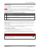
WI-I/O 9-L Configuration Manual The WI-I/O 9-L product provides economical standard “off the shelf” wireless I/O (i.e. transmitting signals over long distances via radio). The WI-I/O 9-L can monitor and control the following types of signals: Signal Examples Digital on/off signals Outputs such as motor run, siren on, etc. Inputs such as motor fault, tank overflow, intruder alarm, etc. Analog continuously variable signals (0-20mA) Outputs such as tank level indication required motor speed, etc.
WI-I/O 9-L Configuration Manual Feature Description For more information, see … Mappings Lets you configure which inputs are sent to which outputs. Mappings can be triggered on a change of state (event reporting) or on a timed basis (periodic update). Sending data to another station using mappings on page 62 Outputs can be physical outputs or Gateway registers. Discrete signals Lets you monitor discrete (on or off) signals such as level switches and alarms. The WI-I/O 9-L-T has two discrete inputs.
WI-I/O 9-L Configuration Manual The WI-I/O 9-L family of modules includes both a transmitter (WI-I/O 9-L-T) and a receiver (WI-I/O 9-L-R). You can: Send signals from the transmitter to the receiver; Send signals from the transmitter to other Weidmuller, Inc. I/O modules; and Send signals from other Weidmuller, Inc. I/O modules to the receiver.
WI-I/O 9-L Configuration Manual The transmitter monitors inputs for changes, and forwards information about the state of the inputs to other modules based on the mapping configuration. Mappings define when to send information about the inputs to remote modules. Mappings can be triggered by a change of value of one of the inputs or after a specified time has elapsed since the last transmission of the information.
WI-I/O 9-L Configuration Manual The receiver receives messages and updates its outputs according to the radio messages. When the module receives a radio message, the yellow LED on the front panel flashes. The receiver provides one analog output (4-20 mA), and three discrete relay outputs. The receiver also provides two status outputs, indicating module OK and communication failure.
WI-I/O 9-L Configuration Manual This section describes how to configure your WI-I/O 9-L. Note For more information on installing your WI-I/O 9-L, please see the WI-I/O 9-L Installation Guide. You can configure your network using: User-defined (customized) configuration – that lets you set specific information about your network and allows communication with other Weidmuller, Inc. I/O modules. Default factory configuration – that lets you use a transmitter and receiver as a simple send/receive pair.
WI-I/O 9-L Configuration Manual Other signals WI-I/O 9-L-T(Transmitter) WI-I/O 9-L-R (Receiver) Thermocouple Input (Not used) Communication Failure (All timeouts set to 10 seconds) Setpoint Output (Local indication) System OK (On if system OK) WI-I/O 9-L Wireless I/O System OK (On if system OK) page 15 of 108
WI-I/O 9-L Configuration Manual The basic steps for configuring your WI-I/O 9-L are: 1. Install the WI Series Software program on your PC. Note WI Series can also configure other Weidmuller, Inc. units. For more information on other Weidmuller, Inc. units, please see the product documentation. 2. Connect your WI-I/O 9-L unit to the PC using the RS-232 serial cable. 3. Configure your WI-I/O 9-L as required using the following steps: Step Description For more information, see … 1.
WI-I/O 9-L Configuration Manual WI Series requires the following minimum PC configuration: Setting Additional information Operating system Windows 98 or later Processor Pentium or greater Memory Minimum 128 Mb Disk space 5 Mb for WI Series 17 Mb during installation 1M (approximately) for each project Serial port 1 serial port RS232 serial cable EIA-561 (RJ45) to EIA-574 (DB9) Weidmuller, Inc. provided serial cable.
WI-I/O 9-L Configuration Manual WI Series lets you configure units using a configuration software program.
WI-I/O 9-L Configuration Manual Installing the configuration software To change the configuration of your module you must install the WI Series software. To install the WI Series software: 1. Insert the CD. 2. Run setup.exe. 3. The installation wizard will guide you through the installation process. WI Series lets you configure an entire communication network, and lets you work with your module to communicate and transfer information between the module and your PC. To start WI Series: 1.
WI-I/O 9-L Configuration Manual Exiting WI Series lets you close the software for communicating and transferring information between the unit and your PC. To exit WI Series: 1. Select File » Exit. 2. WI Series automatically exits. ! " Information about the version of software running on your PC is important for contacting Weidmuller, Inc. if you have support issues. To check the current software version: 1. Select Help » About. 2. WI Series shows the software version information: 3.
WI-I/O 9-L Configuration Manual WI Series lets you create a “project” that stores information for your “system”. Each project can contain one or more units that correspond to a hardware module. Each unit has specific settings and information as shown in the following table: Information Example Project and units Individual units Module (i.e. unit-specific) information As you build the configuration, WI Series automatically saves the information in the Project directory.
WI-I/O 9-L Configuration Manual ! # WI Series lets you create new projects. To create a new project: 1. Click Open New Project or select File » New Project: Note If you are already working with an open project, WI Series confirms you want to close the currently open project: Click Yes to close the open project or click No to return to the current project. 2.
WI-I/O 9-L Configuration Manual 4. WI Series confirms that you want to create the new directory: 5. Click OK to create the new project or click Cancel return to the previous screen without creating a new project. 6. WI Series creates the new project and opens the project: 7. You can now start configuring the project / system.
WI-I/O 9-L Configuration Manual $ % & # WI Series lets you open the last opened project. You can alternatively open any existing project. For more information, see Opening any project on page 25. To re-open the last project: 1. If you have opened a project, WI Series shows the project name on the startup screen: 2. Click Re-open Previous Project . 3. WI Series automatically opens the previous project 4. You can now start configuring the system.
WI-I/O 9-L Configuration Manual # WI Series lets you open any project. You can also open the last opened project. For more information, see Re-opening the last project on page 24. To open any project: 1. Click Open Existing Project or select File » Open Project. 2. Navigate to the directory that holds the project you want to open. If you double click the directory in the browse window, WI Series automatically fills in the project name. Alternately enter the name of the project you want to open: 3.
WI-I/O 9-L Configuration Manual # WI Series shows project information using an hierarchical “tree view” that lets you show or hide information as required. To show project information, click the Plus sign click the Minus sign Show information to show (i.e. expand) the information or to hide (i.e. collapse) the information: Hide information The unit name also shows the unit address: Note The unit name is a default name for the unit. You can change this name to (e.g. Pump Station 14).
WI-I/O 9-L Configuration Manual WI Series lets you sort the tree view: By name – that shows the units in alphabetical order of their unit names; or By address – that shows the units in numerical order of their unit addresses. To sort the tree view: 1. Open the project. 2. Select View » Sort Tree View » by Name (or by Address). 3.
WI-I/O 9-L Configuration Manual # WI Series lets you set the following project information: Field Description For more information, see … Project name Lets you set a name to uniquely identify the project. Setting the project name on page 29. Project location Lets you set the location on your PC where WI Series will store the project. Setting the project location on page 30. Project password Lets you set or remove a password to help protect the configuration file against unauthorized changes.
WI-I/O 9-L Configuration Manual WI Series uses a project name to uniquely identify your system. Each system can have multiple units of different types. To set the project name: 1. Open the project. 2. WI Series shows the project name: 3. Change the project name as required.
WI-I/O 9-L Configuration Manual WI-I/O 9-L stores project information in a “Projects” directory with each individual project stored in a separate directory. The default project directory is \Projects. For example, If you want to change the project location, you must backup the project and then restore the project to the new location. For more information on backing up and restoring projects, see Backing up projects on page 39 and Restoring projects on page 41.
WI-I/O 9-L Configuration Manual WI Series uses a system address to group modules in a system. Modules ignore messages from modules not sharing share their system address to prevent “cross-talk” between modules in different systems. Separate networks with different system addresses can operate independently in the same area without affecting each other. The system address can be any number between 1 and 32 767.
WI-I/O 9-L Configuration Manual 3. Click Set Field original value. to set the new value or click Cancel Field to keep the 4. WI Series confirms you want to change the system address: 5. Click OK to change the system address or click Cancel to quit without changing the system address. 6. WI Series automatically changes the system address.
WI-I/O 9-L Configuration Manual ! " WI Series lets you set a system security code to help ensure the messages that your network uses remain private. This provides an additional security layer to protect the system from malicious access (e.g. hacking). When security is enabled the WI-I/O 9-T uses the security code to encrypt all transmitted radio messages and the WI-I/O 9-R will only receive messages encrypted with the same security code. Note By default, the WI-I/O 9-L does not encrypt radio messages.
WI-I/O 9-L Configuration Manual 4. If you modify the security code, WI Series prompts you to confirm the code by reentering the code: Note The security code can be 1 to 8 characters or numbers and is case-sensitive. A longer security code is stronger (i.e. offers a higher level of security) than a shorter security code To ensure the security code remains confidential, WI Series shows a hash character (i.e. “#”) for each letter or number entered; WI Series never shows the security code in plain text. 5.
WI-I/O 9-L Configuration Manual " WI Series lets you set or remove a system security code to help keep the communications of your system private and to protect the system from malicious access (e.g. hacking). For more information on setting the security code, see Encrypting messages by setting a security code on page 33. To remove the security code: 1. Open the project. 2. Unselect Enable Security: 3. WI Series confirms you want to remove the security code: 4.
WI-I/O 9-L Configuration Manual " " # WI Series lets you set a password (between 6 and 256 characters) to help protect the configuration file against unauthorized changes. If you set a password, you need to enter the password each time you enter the project to: Change - the configuration; Download - the configuration; or Upload - the configuration. Note If you do not enter the password you can still view the configuration; however you cannot make changes.
WI-I/O 9-L Configuration Manual 5. Enter the password (6 to 256 characters) you want to use for the project and then reenter to confirm the password. Note The password can be between 6 and 256 characters long and is case-sensitive. You can enter any ASCII characters (including letters, numbers, other keyboard characters, etc.). To ensure the password remains confidential, WI Series shows a hash character (i.e. “#”) for each letter or number entered; WI Series never shows the password in plain text. 6.
WI-I/O 9-L Configuration Manual # To remove the project password: 1. Open the project. 2. Click Project Password . 3. WI Series shows the Project page. 4. Unselect Enable Project Password: 5. WI Series checks you want to remove the project password: 6. Click OK to remove the project password or click Cancel to return to the password entry page without removing the project password. 7. WI Series removes the project password: 8. Click OK to leave the password entry page.
WI-I/O 9-L Configuration Manual " # WI Series lets you save a project on your PC. You can set the location where you want to save the project. Note WI Series packs the database before saving. The database is then compressed to a single file using the ZIP file format. You can copy this file to another computer or store it on removable media. To backup a project: 1. Open the project. 2. Select File » Backup Project.
WI-I/O 9-L Configuration Manual 6. Click Save to backup the project or click Cancel to return to the previous screen without backing up the project. 7. WI Series backs up the project and shows a message indicating the backup was successful: 8. Click OK to acknowledge the message.
WI-I/O 9-L Configuration Manual $ # WI Series lets you recover a project that has been backed up. This project could be stored on your PC or on removable media (e.g. USB drive or CD). To restore a project: 1. Open the project. 2. Select File » Restore Project. 3. WI Series prompts you to enter the location from where you want to restore the project: 4. Select the project you want to restore and click Open to restore the project or click Cancel to quit without restoring the project.
WI-I/O 9-L Configuration Manual 6. If the location where you want to restore the project already contains a project, WI Series checks if you want to overwrite the existing project. 7. If the directory does not already exist, WI Series checks you want to create the directory: 8. Click OK to create the new directory or click Cancel to return to the previous screen without creating the new directory. 9.
WI-I/O 9-L Configuration Manual WI Series lets you: If you want to … Description For more information, see … Create new units Lets you add new units by creating a new unit, copying an existing unit. Creating new units on page 44. Delete units Lets you remove a unit from the system. Deleting units on page 60. Setting unit information Lets you set mandatory information for all units in a system regardless of the type of unit: Setting unit information on page 52.
WI-I/O 9-L Configuration Manual ! WI Series lets you: If you want to … Description For more information, see … Add a new unit Lets you add a new unit. Creating and adding a new unit to the configuration on page 45. Copy an existing unit Lets you add a new unit by copying an existing unit. Duplicating a unit on page 47. Load a new unit Lets you load a new unit from an already-configured module. Reading configuration from a module (loading a new unit) on page 49.
WI-I/O 9-L Configuration Manual $ #" %" To create and add a new unit to the configuration: 1. Open the project. 2. Select the Units branch of the navigation tree: 3. Click Add New Unit or select Unit Options » New Unit. 4. WI Series shows the Select Unit Type page: 5. Select the unit type you want to add. 6. Click OK to add the new unit or click Cancel without adding the new unit. to return to the previous screen 7. WI Series checks whether you want to choose the address of the new unit: 8.
WI-I/O 9-L Configuration Manual 10. If you choose to set the address, WI Series prompts you with a page showing the addresses already used in the system: 11. Select an unused address and click OK click Cancel to assign the address to the new unit or to return to the previous screen without creating a new unit. 12. WI Series creates the new unit: 13. You can now configure the new unit.
WI-I/O 9-L Configuration Manual &" " ' %" " WI Series lets you add a new unit by copying an existing unit. WI Series copies all the configuration information for the unit. This option is useful for creating a new unit with a similar configuration to an existing unit. To copy a unit: 1. Open the project. 2. Select the unit you want to copy. 3.
WI-I/O 9-L Configuration Manual 6. If you allow WI Series to automatically select the address, WI Series will choose the lowest unused unit address. If you choose to set the address, WI Series shows a page indicating the addresses already used in the system: 7. Select the address and click OK click Cancel to assign the address to the duplicated unit or to return to the previous screen without duplicating the unit. 8.
WI-I/O 9-L Configuration Manual %" % " #" To load a new unit from an already-configured module: 1. Open the project. 2. Connect the module that you want to load to one of your PC serial ports using the Weidmuller, Inc. RS-232 serial cable. 3. Select the serial port that has the cable connected by clicking on the Com Port field and selecting the appropriate port from the list that appears (this step can be skipped if the correct serial port is already selected): 4.
WI-I/O 9-L Configuration Manual 8. WI Series loads the contents of the connected module and may show one or more of the following errors: Error Description and action If there is no module connected to the serial port you have selected or WI Series cannot communicate with the module the following message is shown: Click OK to acknowledge the message and check the power to the module, the comm port selected and the serial cable/connections to try again.
WI-I/O 9-L Configuration Manual Error Description and action match the unit you are loading or No to keep the existing system address already being used by other units in the system. If you choose to change the existing system address all the existing modules must be reprogrammed before the update is complete. If you choose to keep the existing system address you must program the unit you are loading so that it will have the same system address as the rest of the system. 9.
WI-I/O 9-L Configuration Manual Every unit in a system has specific information configured for all units regardless of the type of unit. This information includes: Unit name – you can use this name to refer to the unit when configuring mappings from other units. Unit Address- unique address assigned to the unit. Some module types have two addresses (e.g. WI-I/O 9-3 and WI-I/O 9-4).
WI-I/O 9-L Configuration Manual " WI Series lets you set the unit name to a name that is more meaningful to you. For example, you can initially configure a unit called WI-I/O 9-1#14 and then change the name to Pump station 14. To set the unit name: 1. Select the unit you want to change. 2. Enter the new unit name WI Series automatically updates the unit name in the unit information and also in the unit listing at the side of the page.
WI-I/O 9-L Configuration Manual " WI Series lets you set the unit address used by the system when sending messages to a module. A valid unit address for the WI-I/O 9-L module is between 1 and 95. Note You cannot use a unit address of 0. A network can have up to 95 addresses communicating via radio (i.e. unit addresses 1 to 95). Other I/O-series modules support up to 31 serial modules communicating via RS-485. The upper unit addresses are reserved for identifying these serial modules (i.e.
WI-I/O 9-L Configuration Manual To set the unit address: 1. Select the unit you want to change. 2. WI Series shows the unit address: 3. Select Browse 4. WI Series shows the list of unit addresses and indicates the addresses already in use: 5. Select an unused address and click OK to set the new address or click Cancel to return to the previous screen without setting the new address.
WI-I/O 9-L Configuration Manual 6. WI Series changes the unit address: 7. You can also change the unit name to reflect the new address if required. For more information, see Setting the unit name on page 53.
WI-I/O 9-L Configuration Manual " The WI-I/O 9-L-T supports a secondary address that lets you re-use the same unit address for multiple transmit-only units. This is useful if your network has a large number of transmitonly units. To re-use the same address: Note To use the same address you must have an existing WI-I/O 9-L-T unit. 1. Create a new WI-I/O 9-L-T. 2. WI Series checks if you want to manually set the address: 3. Click Yes to manually set the address.
WI-I/O 9-L Configuration Manual # " " The unit summary lets you print a summary of the information set for the unit. To show and print the unit summary: 1. Open the project. 2. Select the unit for showing the summary. 3. Click Unit Summary . 4. WI Series shows the unit summary: Note The Unit Summary may span multiple pages. You can use the navigation keys at the top of the report to move to the first, previous, next or last pages: 5. To print the unit summary, click Print . 6.
WI-I/O 9-L Configuration Manual # " The unit mappings lets you print a summary of the mapping information for the unit. To show and print the unit summary: 1. Open the project. 2. Select the unit for showing the summary. 3. Click Mapping Summary . 4. WI Series shows the unit mapping: 5. To print the unit summary, click Print . 6. WI Series automatically submits the job to the printer.
WI-I/O 9-L Configuration Manual & Deleting units lets you remove a unit from the system. To delete a unit: 1. Open the project. 2. Select the unit you want to delete 3. Right click and from the shortcut menu select Delete Unit. You can also click Delete Unit in the Unit Options panel of the unit screen: Note If you do not select a unit to delete, WI Series shows the following message: Click OK to acknowledge the message and select the unit you want to delete.
WI-I/O 9-L Configuration Manual 4. WI Series checks you want to delete the unit: 5. Click Yes to delete the unit or click No to return to the previous screen without deleting the unit. 6. WI Series automatically deletes the unit.
WI-I/O 9-L Configuration Manual This section contains specific information for configuring your WI-I/O 9-L-T unit. To send data from a transmitter module WI-I/O 9-L-T to another I/O series module you must configure mappings in the transmitter unit. Mappings let you link inputs at the transmitter unit to outputs at another I/O series module and lets you configure which inputs are sent to which outputs. Mappings can be triggered on a change of state (event reporting) or on a timed basis (periodic update).
WI-I/O 9-L Configuration Manual ' () ( *'++() , % - .%/%0 (/12 WI Series lets you add mappings to define how the system shares information. Conceptually a mapping takes the value of an input and shares it with another module, usually by setting the state of one of the module outputs. The mapping display shows all inputs (including physical inputs and internal inputs) for the selected module. WI-I/O 9-L-T transmits messages only; it cannot receive messages and has no communication failure contingency.
WI-I/O 9-L Configuration Manual To add a new mapping: 1. Open the project and select the unit where you want to add the mapping. 2. Select Mappings. WI Series shows the mapping list: 3. Click New Mapping WI-I/O 9-L Wireless I/O .
WI-I/O 9-L Configuration Manual 4. WI Series shows the mappings page that contains information on two tabs: Tab Example Mapping Advanced 5. Set the required information. For more information, see How to configure a mapping on page 66. to set the mapping or click Cancel 6. Click OK creating a new mapping. to return to the mapping list without 7. WI Series creates the new mapping and displays the mapping in the mapping list. 8. The module will not use the new mapping until you reconfigure it.
WI-I/O 9-L Configuration Manual 0 ! (3) $ ' *'++() Mappings configure when to send specific information to another module and how the data is sent. You can send input data: When the input values change (also called “Event reporting”); or Event reporting and on a timed basis (also called “Timed Update”). Mappings cause the WI-I/O 9-L-T to transmit messages when any of the inputs used by the mapping change state. You can also configure your unit to send messages if there are no state changes for a while.
From inputs This selects the actual input data the WI-I/O 9-L-T will send. The WI-I/O 9-LT sends data to the output module in the order listed. Select the inputs you want to send to the remote module by dragging them from the Available Inputs box or by double-clicking the relevant inputs. Alternatively you can right click on the inputs in the Available Inputs list and select Add to list: Any of the available inputs can be added to the From Inputs box in any order, including the same input multiple times.
WI-I/O 9-L Configuration Manual ! '() () ( 0 *'++() WI Series lets you change an existing mapping. To change unit mappings: 1. Open the project. 2. Select the unit you want to change: 3. Select Mappings. 4. Select the mapping you want to change and click Edit Mapping . 5. WI Series shows the mapping information: 6. Change the mapping information as required. For more information, see How to configure a mapping on page 66. 7. Click OK mapping.
WI-I/O 9-L Configuration Manual / 0 () ( 0 *'++() WI Series lets you delete an existing mapping. To delete unit mappings: 1. Open the project. 2. Select the unit you want to change. 3. Select Mappings. 4. Select the mapping(s) you want to delete. Note You can also Shift+Click and Ctrl+Click to select multiple mappings. 5. Click Delete or right click and click Delete or click Del on your keyboard. 6. WI Series confirms you want to delete the selected mapping(s): 7.
WI-I/O 9-L Configuration Manual Unit sensitivities indicate the change required in an analog input for the WI-I/O 9-L-T to detect a state change and trigger any mapping that includes the input. If you set the sensitivity to a small value, the mappings using the input will trigger on a small change of value. If the input is noisy or variable, this can congest the radio channel by sending multiple spurious messages. You can overcome this situation by increasing the sensitivity value.
WI-I/O 9-L Configuration Manual ! 4 & Pulsed inputs let you count the number of transitions occurring on an input or the rate those transitions occur. WI Series lets you set: Pulsed input rate – detects the rate of transitions on an input. Note The WI-I/O 9-L-T does not support pulsed input rate. Pulsed input count – that counts the number of low-to-high transitions occurring on the input.
WI-I/O 9-L Configuration Manual 7. WI Series shows the range of values you can enter: 8. Click OK to change sensitivity of the pulsed input count or click Cancel to return to the pulsed input screen without changing the sensitivity of the pulsed input count. 9. WI Series will write the new sensitivity value to the module when you reconfigure it.
WI-I/O 9-L Configuration Manual Setpoints let you generate a discrete setpoint status signal based on the value of an analog input. Each setpoint status is associated with two setpoint values - a high threshold value and a low threshold value. When the analog level moves above the high setpoint value, the setpoint status turns off. When the analog level moves below the low setpoint value, the setpoint status turns on.
WI-I/O 9-L Configuration Manual Feature Description Thermocouple setpoint This setpoint is associated with the thermocouple input and can also be configured to read millivolt values. Example You can select one of ten different low setpoint/high setpoint pairs by changing the position of the rotary switch on the front panel of the WI-I/O 9-L-T module.
WI-I/O 9-L Configuration Manual To set setpoints: 1. Open the project. 2. Select the unit you want to change. 3. Select Setpoints. 4. WI Series shows the setpoints: 5. Double click the setpoint you want to change or select the setpoint and click Edit Setpoint. 6. WI Series shows the setpoint: 7. Set the setpoint threshold values as required 8. Set the new value and click OK to save the setpoint or click Cancel to return to the setpoint list without changing the setpoint. 9.
WI-I/O 9-L Configuration Manual " & 4& Thermocouple tables let you measure millivolt signals (-100 to 100 mV) and thermocouple signals with cold junction compensation. WI Series supports the following thermocouple linearization tables: Millivolt Inputs (No linearization); E, J, K, T tables; or User-defined tables.
WI-I/O 9-L Configuration Manual " ! WI Series lets you set the thermocouple that you want to use with your module The thermocouple measurement system works in conjunction with the on-board cold-junction temperature measurement to provide cold-junction compensation using the following options: Enable Cold Junction Compensation - this option is normally selected unless you are using an external cold junction compensation circuit.
WI-I/O 9-L Configuration Manual Table type Description Example 4mA output. High is the value that corresponds to a 20 mA output. User-defined tables For other thermocouple types, you can enter your own user-defined thermocouple linearization and cold-junction compensation tables.
WI-I/O 9-L Configuration Manual $ " % " ! WI Series lets you create your own customised thermocouple tables. You may want to create your own thermocouple tables if the: • Configuration software does not support the type of thermocouple you want to use; or • You want to match the table to the calibration of a particular thermocouple sensor. You should normally enter both cold-junction compensation tables and linearization tables for your thermocouple type.
WI-I/O 9-L Configuration Manual 7. Enter the new value: Fill the cold-junction table with the millivolt output of the thermocouple corresponding to each 10-degree temperature increment. Your thermocouple documentation should contain this information. The Linearization table lets you enter up to 51 data points relating the thermocouple voltage to the desired output value. You can enter the desired output value either as a milliamp value (range 0-20 mA) or as a raw 16-bit unsigned value.
WI-I/O 9-L Configuration Manual & & This section describes how to set additional unit detail information including: Sample period and warmup time - the WI-I/O 9-L-T only turns on the analog circuits and the +24V analog loop power supply when they are actually required. You can reduce the module power consumption by limiting the amount of time the analog circuitry and the +24V analog loop supply is enabled. Sample period determines how often the module checks an analog signal.
WI-I/O 9-L Configuration Manual Feature Description Thermocouple warm up time The amount of time the analog circuits are turned on before sampling the thermocouple input. Example For normal thermocouples, these can be set to the minimum value (i.e. 0.08 seconds). If using an external (millivolt) device powered from the +24V supply that requires a longer period to settle, you may need to set this value to allow the external device to settle.
WI-I/O 9-L Configuration Manual Feature Description Ain1 debounce The debounce time is the product of the number of samples and the sample period. The signal must differ from the previous value by the sensitivity value for this duration to register a ‘change of state’. Example This means that changing the analog sample time will also change the debounce time. For analog signals, a value of 0 or 1 generates the quickest response; 255 generates the slowest response.
WI-I/O 9-L Configuration Manual Feature Description Din2 Debouce The amount of time the second digital input must stay in a changed state before it registers as a change of state. Example To set the additional unit detail information: 1. Open the project 2. Select the unit you want to change. 3. Select Unit Details. 4. WI Series shows the available unit details including their current values: 5.
WI-I/O 9-L Configuration Manual 6. WI Series shows the relevant setting page showing the range of allowable values: 7. Enter the setting information and click OK to change the parameter or click Cancel to return to the detail list without changing the parameter. 8. WI Series will write the unit details to the module the next time you configure the module.
WI-I/O 9-L Configuration Manual ! This section contains specific information for configuring your WI-I/O 9-L-R unit. & & 4 Unit output reset times allow you to configure the outputs to turn off if they do not receive an update message within a certain time. The output is reset to a zero value if it does not receive an update message within the configured time. The output is turned off for discrete outputs.
WI-I/O 9-L Configuration Manual " WI Series lets you view a summary of your system information and optionally print the information. If you want to … Description For more information, see … Set your printer information Lets you specify the printer and settings you want to use for printing information. Setting printer information on page 87. Show unit summary Lets you view and print the user options configured for the unit. Showing and printing the unit summary on page 58.
WI-I/O 9-L Configuration Manual # $ Utilities provide one-step access to help speed up common tasks. WI Series lets you: If you want to … Description For more information, see … Show address mapping Lets you see the addresses allocated to units. Showing the address mapping on page 89. Compile the system Lets you check your system configuration, report any errors and generate configuration files for each unit. Compiling the system on page 90.
WI-I/O 9-L Configuration Manual WI Series lets you see the addresses allocated to units. This summarises the addresses of each module in a single screen. To change the address of a module, refer to Setting the unit address on page 54. To show the address mapping: 1. Open the project. 2. Select Utilities » Address Map. 3.
WI-I/O 9-L Configuration Manual ! & After configuring the modules, you can check for errors by compiling the system. Note The system is also compiled before any data is programmed to any of the modules. It is not necessary to compile the system before configuring modules. Compiling the system: Checks - your system configuration; Reports - any errors; and Generates - configuration files for each unit. After compiling the system, you need to upload the configuration files to the units.
WI-I/O 9-L Configuration Manual 5. WI Series compiles the system and shows any errors or warnings: Note You must fix any errors or warnings before using your system. 6. Click Close to close the System Compile page. 7. You can now upload the configuration file to the units. For more information, see Programming the on page 96.
WI-I/O 9-L Configuration Manual + " - 4 WI Series lets you pack (i.e. compress) the database so it takes up less space on your PC. To pack the database: 1. Open the project. 2. Select Utilities » Database Utilities » Pack all Databases. 3. WI Series packs all databases and shows an information message indicating the pack completed successfully: 4. Click OK to acknowledge the message.
WI-I/O 9-L Configuration Manual / After compiling the system, you need to transfer the configuration information to a unit. The basic steps for transferring the configuration information to the unit are: Step Description For more information, see … 1. Connect the unit to the PC Lets you connect the unit to your PC using an RS-232 serial port so you can transfer configuration information between your PC and the unit. Connecting the unit to the PC on page 94. 2.
WI-I/O 9-L Configuration Manual $ " ($ You can connect the WI-I/O 9-L to an RS-232 serial ports on your PC using an Weidmuller, Inc. serial cable. This allows you to transfer configuration information between your PC and the module. If you do not have a serial cable, you can make your own. For more information on cable connection details, see Appendix B on page 105. To connect the unit to the PC: 1. Connect the DB9 end of the serial cable to the RS-232 serial port of your computer.
WI-I/O 9-L Configuration Manual WI Series transfers configuration information between your PC and the WI-I/O 9-L using serial ports. You must set the serial port to use for transferring the configuration information. This is the serial port that has the configuration cable connected to the module you are programming. To set the serial port: 1. Open the project. 2. Select Utilities » Serial Port Setup. 3. Select the serial port you want to use for configuring the unit (e.g. Com 1): 4.
WI-I/O 9-L Configuration Manual ( " ! % % % ($ " WI Series transfers the configuration information between the module and your PC using a serial port. Note You must set the serial port before loading the configuration. For more information, see Setting the serial port on page 95. To program the unit (i.e. write the information form the PC to the module): 1. Open the project. 2. In the tree view, select the unit you want to program. 3.
WI-I/O 9-L Configuration Manual Note If the unit address of the module you are programming does not match the address of the configuration that you are sending, WI Series shows the following warning: This helps ensure that you program the correct module. Check the module that you are programming should have its unit address changed. If this is the correct module, click OK.
WI-I/O 9-L Configuration Manual % % % " ($ WI Series transfers the configuration information between your PC and the module using a serial port. Note You must set the serial port before transferring the configuration. For more information, see Setting the serial port on page 95. To load the configuration information (i.e. transfer the information from the module to the PC): 1. Open the project. 2. Select the unit you want to load. 3. Click Load Unit . 4.
WI-I/O 9-L Configuration Manual 6. WI Series checks the unit’s current configuration to determine if the user configuration is valid. If the user configuration is valid and the module is currently configured to use its factory configuration, WI Series shows the following message to let you select the configuration to load: 7. Click Yes to factory configuration or click No to select previously stored (i.e. inactive) user configuration.
WI-I/O 9-L Configuration Manual %$ WI-I/O 9-L modules have a diagnostic tool that lets you monitor radio communications to help you troubleshoot (i.e. fix) problems with your unit. The diagnostic tool checks communications between the unit and your PC. On the WI-I/O 9-L-T - you can read the status of the inputs. On the WI-I/O 9-L-R - you can monitor the radio communications.
WI-I/O 9-L Configuration Manual * % - .%/%$ To monitor radio communications on a WI-I/O 9-L-R: 1. Select the unit you want to troubleshoot. 2. Click Diagnostics . 3. WI Series starts the diagnostic tool: 4. Click Start Comms. 5. The display shows the radio messages received. Messages starting with RX indicate a received message, WI Series also shows the RSSI (radio signal strength indication) in dBm at the end of each received message.
WI-I/O 9-L Configuration Manual 6. To view additional information about a message, select the message line with the mouse. WI Series shows additional information about the message at the bottom of the screen including the system address, RSSI and CRC (i.e. error-check) status. The “text box” in the bottom middle of the screen decodes the message to display the I/O channel and value.
WI-I/O 9-L Configuration Manual ! " % - .%/%0 To check the status of inputs on a WI-I/O 9-L-T: 1. Navigate to the Unit page for the unit you want to check. 2. Click Read Inputs. 3. WI Series shows a page indicating the status of all inputs to the module: 4. Click Update to read the status of the inputs from the module. 5. For analog values (i.e..
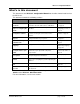
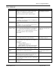
WI-I/O 9-L Configuration Manual & '& ( %$ $ $ $ Raw value 4-20mA Supply voltage Module Temp Millivolt 0-100% Thermocouple E J K T 0 - - - - - - - - 2048 - - - - - - - - 4096 - - - - - - - - 6144 - - - - - - - - 8192 0 - - - - - - - 10240 1 - - - - - - - 12288 2 - -12.5 - - - - - 14336 3 - -6.25 - - - - - 16384 4 0 -40°C 0.00 0.00 -200.00 -200.00 -200.00 -200.00 18432 5 2.5 -30°C 6.25 6.25 -125.00 -112.
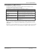
WI-I/O 9-L Configuration Manual & ') ( %$ You can connect the WI-I/O 9-L to an RS-232 serial port on your PC using an Weidmuller, Inc. serial cable to transfer configuration information between your PC and the module.
WI-I/O 9-L Configuration Manual *$ This document uses the following terms: Term Meaning Analog signal Analog signals are continuously variable signals. The WI-I/O 9-L supports analog signals in the range 0-20 milli-amps Cold junction temperature compensation When using thermocouples, the module compensates for the reading errors caused by the temperature of the connection between the thermocouple wires and the module terminal strip.
WI-I/O 9-L Configuration Manual ' A address mapping showing.................................................................. 89 Ain1 warm up time.......................................................... 83 analog setpoints ......................................................... 73 B basic steps.................................................................. 16 battery sample rate ............................................................ 82 battery low setpoints....................................
WI-I/O 9-L Configuration Manual sample rate battery .................................................................... 82 thermocouple ................................................... 81, 83 security code removing ................................................................ 35 setting .................................................................... 33 serial ports .................................................................. 95 setting .....................................................