Installation Manual WI-I/O 9-L-x Wireless I/O
Document information Installation Manual WI-I/O 9-L-x Wireless I/O Version 1.6 Weidmuller Inc. contact details Address > 821 Southlake Blvd., Richmond, VA 23236 Telephone > (800) 849-9343 Fax > (804) 897-4134 Email > support@weidmuller.com Website > www.weidmuller.com Copyright Limited lifetime warranty, disclaimer and limitation of remedies Weidmuller Inc. products are warranted to be free from manufacturing defects for the “serviceable lifetime” of the product.
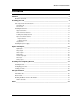
WI-I/O 9-L-x Installation Guide Contents __________________________________________________________________ 3 About this document ............................................................................................................................ 6 Installing your unit __________________________________________________________ 7 Unit components and connections....................................................................................................... 8 Transmitter unit .................
WI-I/O 9-L-x Installation Guide This page intentionally left blank. WI-I/O 9-L-x v1.
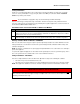
WI-I/O 9-L-x Installation Guide Safety information Thank you for selecting the WI-I/O 9-L-x for your telemetry needs. We trust it will give you many years of valuable service. To ensure your WI-I/O 9-L-x enjoys a long life, double-check ALL your connections with the Installation Guide before powering on the module. WARNING: Incorrect termination of supply wires may cause internal damage and will void warranty. Exposure to RF energy is an important safety consideration.
WI-I/O 9-L-x Installation Guide This document is the WI-I/O 9-L-x Wireless I/O Installation Manual that describes how to install your WI-I/O 9-L-x units and contains important information for installing your units with other equipment. Note If your network only contains one transmitter and receiver pair, you should also read the WI-I/O 9-L-x QuickStart Guides.
WI-I/O 9-L-x Installation Guide This section describes how to install your unit and contains the following sections: Step Description 1 – Read the safety information Lets you understand important safety information related to your unit. NOTE: You must read this information before installing your unit. For more information, see … Safety information on page 5. 2 – Get to know the unit features Understand the basic features of your unit. Unit components and connections on page 8.
WI-I/O 9-L-x Installation Guide This section shows the components and terminal connections for the transmitter and receiver units. Your transmitter unit has the following components and terminal connections: WI-I/O 9-L-x v1.
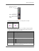
WI-I/O 9-L-x Installation Guide The front panel contains the following components: SMA antenna connector SMA connector at top ofantenna unit top of unit at RS232 configuration port RS232 configuration port Rotary switch for set-point Rotary switch for set-point settings settings The triangle on the rotary switch indicates the current position, for example: Position 0 Position 1 NOTE: To avoid damaging the rotary switch, use a screwdriver to change the position.
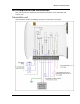
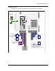
WI-I/O 9-L-x Installation Guide Your WI-I/O 9-L-x unit has the following components and terminal connections: Earth wire lug underneath unit - DO 3 - DO 2 - DO 1 NOT USED NOT USED - + POWER SUPPLY - AO DO 2 DC LOAD DO 1 LOAD Max. 30VDC 500mA + For inductive load, use surge diodes + LOAD SYSTEM OK COMMS FAIL COMMON + 24V + - DO 3 - AC LOAD ANALOG OUTPUT Max. analog load 900 ohm + - + POWER SUPPLY 9 – 30 VDC 250mA @ 12V WI-I/O 9-L-x v1.
WI-I/O 9-L-x Installation Guide The front panel contains the following components: SMA antenna connector at top of unit SMA antenna connector at top of unit RS232 configuration RS232 configuration port port RSSI push-button RSSI push-button The LEDs on the front panel indicate the unit status: LED Status Indicates None No power supply. OK LED Green Current status of the unit OK. OK LED Red Fault condition detected in unit. RX Led Flashes Receiving Message.
WI-I/O 9-L-x Installation Guide This section explains how to install your antenna and contains the following sections: Section Description For more information, see … Supported antennas and cables Details the antennas and cables you can use with the units. Supported antennas on page 12. Radio transmission distances Details the distances for reliable operation. Radio transmission distances on page 14.
WI-I/O 9-L-x Installation Guide You must carefully select antennas for WI-I/O 9-L-T modules to avoid contravening the maximum power limit on the unlicensed channel. The net gain of the antenna/cable configuration should be no more than 6dB in North America (USA, Canada, Mexico) and no more than 0 dB in Australia / New Zealand. Note The net gain of an antenna/cable configuration is the gain of the antenna (in dBi) less the loss in the coaxial cable (in dB).
WI-I/O 9-L-x Installation Guide The unit will operate reliably over large distances depending on the: Antenna type; Antenna location; Amount of radio interference; and Radio path obstructions (e.g. hills or trees). Typical reliable distances are: Area Distance Additional information USA/Canada 20+ miles 6dB net gain antenna configuration permitted (4W Equivalent RF power permitted). Australia/NZ 20+ km Unity gain antenna configuration (1W Equivalent RF power permitted).
WI-I/O 9-L-x Installation Guide You must connect an antenna to each WI-I/O 9-x module using the SMA connector at the top of the enclosure. Weidmuller Inc. recommends carefully taping the connections between the antenna and coaxial cable to prevent moisture ingress. Moisture ingress in the coaxial cable is a common cause of radio system problem as it greatly increases the radio losses. Weidmuller Inc. recommends taping the connection with three layers of tape: Layer Tape 1 PVC tape.
WI-I/O 9-L-x Installation Guide This section contains important information for using dipole and collinear antennas. For more information, see the next sections. Unity gain dipole antennas are commonly used on unlicensed channels. The dipole antenna does not provide any gain, so the power transmitted from the antenna is the same as the power out of the module. A dipole antenna that comes supplied with integral 15 ft cable does not require additional coaxial cable.
WI-I/O 9-L-x Installation Guide The following diagrams shows the recommended installation for collinear and dipole antennas: WI-I/O 9-L-x v1.
WI-I/O 9-L-x Installation Guide Yagi antennas are directional and have positive gain to the front of the antenna and negative gain in other directions. You can use the gain to: Compensate for coaxial cable loss for transmitter unit; and Increase receive sensitivity for receiver units. You should install Yagi antennas with the central beam horizontal and pointed directly in the transmission direction to benefit from the antenna gain. Note Yagi antennas usually have a drain hole on the folded element.
WI-I/O 9-L-x Installation Guide This page intentionally left blank. WI-I/O 9-L-x v1.
WI-I/O 9-L-x Installation Guide The unit works with a 9-30 VDC 1 Amp CSA certified Class 2 power supply. For use in Class 1 Div 2 explosive areas, the power supply must be approved for Class 1 Div 2 use. Warning – explosion hazard Do not disconnect while circuit is live unless area is known to be non-hazardous.
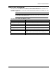
WI-I/O 9-L-x Installation Guide The units have the following inputs and outputs: Input/output WI-I/O 9L-T Digital inputs 2 Relay outputs Status outputs 2 Analog inputs 1 WI-I/O 9L-R Description For more information, see … Suitable for Voltage free contact, NPN transistor, 05V signal. Digital inputs on page 22. 3 250VAC 1A / 30VDC 1A. Relay outputs Important Information on page 23. 2 Max 30VDC, 500 mA. Indicate module status, communication failure and local setpoint status.
WI-I/O 9-L-x Installation Guide The WI-I/O 9-L-T module provides two digital inputs suitable for: Voltage free contacts – e.g. mechanical switches; or NPN transistor devices – e.g. electronic proximity switches; or 0-5V signals - 2V – 4V Minimum range. Note PNP transistor devices are not suitable. The unit provides contact wetting current of approximately 5mA to maintain reliable operation of driving relays. Each digital input is connected between the appropriate Digital Input terminal and Ground.
WI-I/O 9-L-x Installation Guide The WI-I/O 9-L-R module provides three normally open voltage-free relay contacts rated at 250VAC / 50VDC 1A. You can use these outputs to directly control low-powered equipment or power larger relays for higher-powered equipment. For inductive loads, Weidmuller Inc. recommends: DC relays - use flyback diodes across the external circuit to prevent arcing across the relay contacts. DC Load Max 30VDC AC relays – use capacitors (e.g.
WI-I/O 9-L-x Installation Guide The unit contains the following status outputs: System OK; Setpoint Output; and Communications Failure. Status outputs are FET output to common rated at 30VDC 500 mA. Connect the output circuit to the appropriate Status Output terminal. Each status output circuit is associated with an LED indicator that lights lit when the digital output is active.
WI-I/O 9-L-x Installation Guide The WI-I/O 9-L-T module provides one 0 - 20 mA DC analog input for connecting to instrument transducers (e.g. level, moisture, pressure transducers, etc.). Note The WI-I/O 9-L-T module inputs measure down to 0mA and can also be used for zero based signals (e.g. 0 - 10 mA). The analog input has a positive and negative terminal and can be placed at any point in the current loop, providing neither input rises above the 24 volt Analog Loop Supply level.
WI-I/O 9-L-x Installation Guide The following diagrams illustrate different connection methods: Analog signal source Example 2 wire transducer 4 wire transducer Current source output WI-I/O 9-L-x v1.
WI-I/O 9-L-x Installation Guide Analog signal source Example Current sink output WI-I/O 9-L-x v1.
WI-I/O 9-L-x Installation Guide The WI-I/O 9-L-T provides one input suitable for connection to a thermocouple or a millivolt level signal. The module provides linearization tables for J, K and T type thermocouples and also supports other types via a user linearization table. Millivolt signals in the range -10mV to +100 mV are supported. For more information on configuring the thermocouple input and cold-junction compensation to suit your application, refer to the User Manual. WI-I/O 9-L-x v1.
WI-I/O 9-L-x Installation Guide The WI-I/O 9-L-T module lets you configure the digital inputs as pulse inputs with the following characteristics: Characteristic Value Maximum rate 10 Hz Minimum off time 20 mSec Minimum on time 20 mSec Using this mode, you can map the pulse count to a remote output by re-generating as a Pulse Output on WI-I/O 9-1or Digital Output on a WI-I/O 9-3 unit. Note You should connect the pulse input in the same way as a digital input.
WI-I/O 9-L-x Installation Guide The WI-I/O 9-L-R module provides a 4 - 20 mA DC analog output for connecting to instrument indicators to display remote analog measurements. The analog output is a current source provided from an internally generated +24V loop supply. When connecting to an external device (e.g. electronic indicator, recorder, PLC / DCS input, etc.) by connecting the output between the Analog Output terminal (+) and the COM terminal (-).
WI-I/O 9-L-x Installation Guide Connection method Example To singleended input device WI-I/O 9-L-x v1.
WI-I/O 9-L-x Installation Guide This section describes how to install and configure your unit and contains the following sections: Section Description For more information, see … Installing the unit Describes how to physically install your unit. Installing the unit on page 33. Configuring your unit Describes the different ways to configure your unit. Configuring your units on page 34. Testing your unit Describes Weidmuller Inc.’ recommendations for testing your unit.
WI-I/O 9-L-x Installation Guide To install the unit: 1. Connect signals to the supplied terminals. 2. Connect the radio antenna. 3. Install DIN rail to mount the module. 4. Clip the module to the DIN rail: You can now configure your unit. For more information, Configuring your units on page 34. WI-I/O 9-L-x v1.
WI-I/O 9-L-x Installation Guide You can configure your network using: Default factory configuration – that lets you easily setup your network as a simple send/receive; or User-defined customized configuration – that lets you set specific information about your network and allows communication with other Weidmuller Inc. WI-I/O 9-x series devices. For more information on setting a user-defined customised configuration, see the User Manual.
WI-I/O 9-L-x Installation Guide We recommend you bench test the complete system before installing a new system. Configuration problems are easier to identify and fix when the units are next to each other. The following table describes common problems and recommended solutions: If your installation has … You should check … Weidmuller Inc. recommends … Poor radio channel communications • • • • • • TX LED flashes but no RX LED Output LEDs flash quickly The antenna installation.
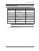
WI-I/O 9-L-x Installation Guide This section details the specifications for each unit. Input/output Number Additional information Digital inputs 2 Dry-contact digital inputs slow-pulsed at 10Hz. All inputs are suitable for voltage free contacts (e.g. mechanical switches) or NPN transistor devices (e.g. electronic proximity switches). NOTE: PNP transistor device inputs are NOT suitable.
WI-I/O 9-L-x Installation Guide This section contains reference information about additional hardware components you may need for your unit. You can connect the unit to a PC using an RS-232 serial cable to: Transfer configuration information; Perform factory and field-testing. The serial port is an 8 pin RJ-45 plug that communicates using standard RS-232 signals: Signal information Value Baud rate 9600 Bits 8 bits with 1 stop bit Parity No parity Weidmuller Inc.
WI-I/O 9-L-x Installation Guide 2 wire transducer ..................................................... 29 4 wire transducer .................................................... 29 AC relays ................................................................. 26 active pulse device ................................................ See active signal device ................................................. 25 analog input ............................................................. 28 analog output.............
WI-I/O 9-L-x Installation Guide specifications ........................................................... 39 status outputs .......................................................... 27 surge diverter........................................................... 18 surge protection....................................................... 18 surge suppression ................................................... 18 switches electronic proximity .............................................