
User Manual

WI-I/O 9-L-x Installation Guide
WI-I/O 9-L-x v1.6 Page 11 of 39
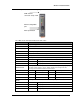
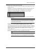
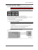
The front panel contains the following components:
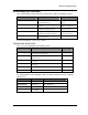
The LEDs on the front panel indicate the unit status:
LED Status Indicates
None No power supply.
OK LED Green Current status of the unit OK.
OK LED Red Fault condition detected in unit.
RX Led Flashes Receiving Message.
CF Led ON Module Communication Failure Output is active.
PG LED on Configuration Cable Connected.
Output LED ON The Output LEDS (i.e. D1, D2, D3) light when the corresponding output is active.
D1 Relay output D1 is ON (Contact Closed).
D2 Relay Output D2 is ON.
D3 Relay Output D3 is ON.
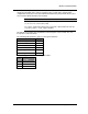
LEDs with RSSI Push
Button Pressed
When you press the RSSI push button, the unit shows the signal strength by lighting
the LEDs from the bottom to the top. Signal strength is the strength of the last
message received that was addressed to this station.
LED Signal Strength LED Signal Strength
D1 More than -85 dBm RX More than -100 dBm
D2 More than -90 dBm CF More than -105 dBm
D3 More than -95 dBm PG Always on during RSSI test
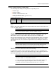
Output LED flashing
quickly
If an output is in communication failure, the corresponding LED flashes at 5 Hz.
D1 Relay Output D1 is in communication failure.
D2 Relay Output D2 is in communication failure.
D3 Relay Output D3 is in communication failure.
PG Analog output is in communications failure.
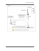
SMA antenna connector
at top of unit
RSSI push-button
RS232 configuration
port
SMA antenna
connector at top of unit
RS232 configuration
port
RSSI push-button