
User Manual

WI-I/O 9-L-x Installation Guide
WI-I/O 9-L-x v1.6 Page 21 of 39
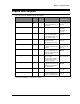
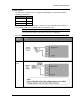
The units have the following inputs and outputs:
Input/output WI-I/O 9-
L-T
WI-I/O 9-
L-R
Description For more
information, see
…
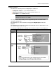
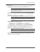
Digital inputs
2
Suitable for Voltage free
contact, NPN transistor, 0-
5V signal.
Digital inputs on
page 22.
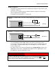
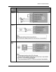
Relay outputs
3
250VAC 1A / 30VDC 1A. Relay outputs
Important
Information on
page 23.
Status outputs
2 2
Max 30VDC, 500 mA.
Indicate module status,
communication failure and
local setpoint status.
Status outputs on
page 24.
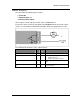
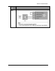
Analog inputs
1
4-20 mA with over-range
and under-range.
0-10 mA with over-range.
Analog input on
page 25.
+24V Loop supply
1
Provides power for 1
external current loop (up to
35 mA).
Installing the
power supply on
page 20.
Analogue setpoint
1
Allows discrete setpoint to
be controlled from analog
input. Threshold adjustable
via rotary switch.
Refer to the User
Manual.
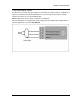
Thermocouple / millivolt input
1
Provides measurement of
E, J, K, T type
Thermocouple, millivolt
signals and user-defined
thermocouple types.
Thermocouple
input on page 28
Thermocouple setpoint
1
Lets you control discrete
setpoint from thermocouple
with threshold adjustable
via rotary switch.
Refer to the User
Manual.
Pulse inputs
2
Up to 10Hz. Pulse input on
page 29.
Analog output
1
0-22 mA, suitable for loop
powered, floating input or
single-ended input device.
Analog output on
page 30.
For more information, see the next sections.