
User Manual


WI-I/O 9-L-x Installation Guide
WI-I/O 9-L-x v1.6 Page 9 of 39
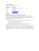
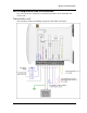
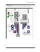
The front panel contains the following components:
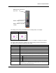
The triangle on the rotary switch indicates the current position, for example:
Position 0 Position 1
NOTE: To avoid damaging the rotary switch, use a screwdriver to change the position.
The rotary switch controls the setpoint levels on the Analog and Thermocouple inputs.
The LEDs on the front panel indicate the unit status:
LED Status Indicates
None No power supply.
OK LED Green Current status of the unit OK.
OK LED Red Fault condition detected in unit.
TX Led Flashes Transmitting Message.
PG LED on Configuration Cable Connected.
Input LED ON Input LEDS (i.e. D1, D2, SP, AZ.) light when the corresponding input is active.
D1 Digital Input 1 is active (Low).
D2 Digital Input 2 is active.
SP Analog Setpoint is active.
AZ Analog Input is zero mA
All LEDs medium flash Medium speed flash (1.6HZ) indicates the module is halfway through the
configuration process. Medium flash also happens when you set the rotary switch
to position 0 when powering on the unit.
SMA antenna connector
at top of unit
Rotary switch for set-point
settings
RS232 configuration
port
SMA antenna connector at
top of unit
RS232 configuration port
Rotary switch for set-point
settings