Industrial Wireless MESH I/O WI-I/O 9-U2 MESH I/O Manual Version 1.2.
Weidmuller USA Corporate Headquarters 821 Southlake Boulevard Richmond, Virginia 23236 804.794.2877 Main 800.849.9343 Customer & Technical Support 804.794.0252 Fax info@weidmuller.com Copyright Weidmüller Interface GmbH & Co. KG | Klingenbergstraße 16 | D-32758 Detmold Thank you for your selection of the WI-I/O 9-U2 I/O Module. We trust it will give you many years of valuable service. ATTENTION! Incorrect termination of supply wires may cause internal damage and will void warranty.
GNU Free Documentation Licence: Copyright (C) 2009 Weidmuller. Weidmuller is using a part of Free Software code under the GNU General Public License in operating the “WI-I/O 9-U2” product. This General Public License applies to most of the Free Software Foundation’s code and to any other program whose authors commit by using it. The Free Software is copyrighted by Free Software Foundation, Inc. and the program is licensed “As is” without warranty of any kind.
FCC Notice: This WI-I/O 9-U2 module uses the “E2_900M Wireless Data Modem” radio and complies with Part 15.247 of the FCC Rules. Operation is subject to the following two conditions: This device may not cause harmful interference This device must accept any interference received, including interference that may cause undesired operation. WI-I/O 9-U2 Radio Telemetry Unit must be installed in a suitable enclosure that provides mechanical, shock and fire hazard protection.
Hazardous Location Notices: This device complies with 94/9/EC – ATEX Directive Ex nA IIC T4A, II 3 G, –40 °C ≤ Ta ≤ +60 °C WARNING: EXPLOSION HAZARD. Do not disconnect equipment unless power has been switched off or the area is known to be non-hazardous. This equipment is suitable for use in Class I, Division 2, Groups A, B, C and D; Tamb -40˚C to +60˚C or non-hazardous locations only.
IMPORTANT Notice: WEIDMULLER products are designed to be used in industrial environments, by experienced industrial engineering personnel with adequate knowledge of safety design considerations. WEIDMULLER radio products are used on unprotected license-free radio bands with radio noise and interference. The products are designed to operate in the presence of noise and interference, however in an extreme case, radio noise and interference could cause product operation delays or operation failure.
TABLE OF CONTENTS CHAPTER 1 - INTRODUCTION ..................................................................................... 12 1.1 Overview ................................................................................................................................................ 12 1.2 Module Structure ................................................................................................................................... 14 1.3 Getting Started ...........................................
3.2.1 Front Panel Indications .................................................................................................................... 37 3.2.2 Boot Sequence “PWR” LED Indications .......................................................................................... 38 3.2.3 Input / Output Indications ................................................................................................................. 38 Digital Inputs .............................................................
4.3.9 I/O Configuration ............................................................................................................................. 61 Digital Inputs ......................................................................................................................................... 62 Digital Outputs ...................................................................................................................................... 62 Pulsed Outputs ..................................
5.4 Neighbour RSSI (WibMesh) .................................................................................................................. 96 5.5 Network Diagnostics (WibMesh) ......................................................................................................... 98 Ping ....................................................................................................................................................... 98 Trace Route ..................................................
TABLE OF FIGURES Figure 1 – Module Structure 14 Figure 2 – Power Connectors .........................16 Figure 3 – Supply Connections .......................16 Figure 37 - ID Address List ............................. 55 Figure 38 - Mappings ...................................... 55 Figure 39 - Gather/Scatter Mapping ............... 57 Figure 4 – Expansion I/O power & RS485 ......18 Figure 40 - Startup/Force .Error! Bookmark not defined. Figure 5 - Earthing ..........................................
Figure 72 - Module Information .......................85 Figure 73 – System Tools ...............................86 Figure 74 - Format USB ..................................87 Figure 75 - Quick Format ................................87 Figure 76 - Firmware Files ..............................87 Figure 77- firmware version ............................88 Figure 78 - Side access panel.........................88 Figure 79 - Firmware Upgrade LED Indications .......................................................
Chapter 1 - Introduction 1.1 Overview The WI-I/O 9-U2 range of I/O modules has been designed to provide standard “off-theshelf” telemetry functions, for an economic price. Telemetry is the transmission of data or signals over a long distance via radio or twisted-pair wire cable. Although the WI-I/O 9-U2 Series is intended to be simple in its application, it provides many sophisticated features, which will be explained in the following chapters.
The WI-I/O 9-U2 modules transmit the input/output data using radio or Ethernet. The data frame includes the "address" of the transmitting module and the receiving module, so that each transmitted message is acted on only by the correct receiving unit. Each message includes error checking to ensure that no corruption of the data frame has occurred due to noise or interference. The module with the correct receiving "address" will acknowledge the message with a return transmission (acknowledgement).
1.2 Module Structure Figure 1 – Module Structure The WI-I/O 9-U2 is made up of a number of basic sections, which all interface with a central Input and output storage area (I/O Store). The I/O Data Store provides storage for I/O data as well as providing services to other processes in the system.
(transistor output). Each I/O point is linked to separate I/O registers within the I/O Data Store. There are also a number of Internal I/O that can be accessed from the I/O Data Store. These inputs can be used to interpret the status of a single module or an entire system Battery voltage – The battery terminal voltage displayed as an Analog value. Loop Supply – Monitors the +24V DC Analog Loop Supply (ALS), used to power analog current loops and displays this as an Analog value.
Chapter 2 - Installation 2.1 General All WI-I/O 9-U2 Series modules are housed in a plastic enclosure with DIN rail mounting, providing options for up to 14 I/O points, and separate power & communications connectors. The enclosure measures 170 x 150 x 33 mm including connectors. The antenna protrudes from the top 2.2 Power/Supply Figure 2 – Power Connectors Figure 3 – Supply Connections 2.2.1 Requirements The recommended power options available for the WI-I/O 9-U2 module are as follows. 1.
reduced to 0.5A at 60°C. If using a battery it is recommended a 10A inline fuse be fitted as prevention against battery short circuit. If utilising option 1 above and the Primary Supply fails the Battery Supply will continue to power the module without interruption to the operation. The Supply and Battery charging terminals are hosted on the 4-way connector on the bottom edge of the module labelled “Supply” Both Supply and Battery connections have reverse polarity and over voltage protection.
2.2.2 Expansion I/O Supply To allow increased I/O Capacity, a second 4-way terminal labelled “Expansion I/O” provides a +12 Volt supply (up to 1A) and RS485 communications for any WI-I/O-EX-1S serial expansion I/O modules. Figure 4 – Expansion I/O power & RS485 As a guide when using the I/O power connection from the WI-I/O 9-U2, the number of I/O modules is limited to three x WI-I/O-EX-1-S-11(using inputs), one x WI-I/O-EX-1-S12, or one x WI-I/O-EX-1-S-13.
2.2.3 Internal I/O The internal supply voltages can be monitored by reading the register locations below. See Section 5.1 “IO Diagnostics” for details on how this can be done. The values can also be mapped to a register or an analog output on another module within the radio network. 30005 Local Supply voltage (0-40V scaling) 30006 Local 24V loop voltage (0-40V scaling) – Internally generated +24V supply used for analog loop supply.
Figure 5 - Earthing 2.3 Radio The following radio variants are available in the WI-I/O 9-U2 dependent on the country of operation. 2.3.1 900 MHz Spread Spectrum radio The radio uses frequency hopping spread spectrum modulation, which is a method of transmitting radio signals by switching the carrier among many frequency channels, using a pseudo random sequence called a hop set.
A spread-spectrum transmission offers some advantages over a fixed-frequency transmission. Spread-spectrum signals are more resistant to narrowband interference. They are difficult to intercept or eavesdrop because of the pseudorandom transmission sequences. Transmissions can share a frequency band with other types of conventional transmissions with minimal interference. 2.3.2 869 MHz Fixed Frequency radio (EU Country Code) This radio operates in the unlicensed fixed frequency band of 869 MHz.
Typical reliable distances are detailed below, however longer distances can be achieved if antennas are mounted in elevated locations – such as on a hill or on a radio mast.
testing to determine if they are reliable - refer section 5.6 “Network Statistics” Where it is not possible to achieve reliable communications between two modules, then a third module may be used to receive the message and re-transmit it. This module is referred to as a repeater. This module may also have input/output (I/O) signals connected to it and form part of the I/O network - refer to Chapter 4 Configuration of this manual. An antenna should be connected to the module via 50 ohm coaxial cable (e.g.
Figure 7 – Collinear Antenna mounting 24
Yagi antennas. A Yagi antenna provides high gain in the forward direction, but lower gain in other directions. This may be used to compensate for coaxial cable loss for installations with marginal radio path. The Yagi gain also acts on the receiver, so adding Yagi antennas at both ends of a link provides a double improvement. Yagi antennas are directional. That is, they have positive gain to the front of the antenna, but negative gain in other directions.
2.5 Connections 2.5.1 Bottom panel connections Figure 9 – Bottom Panel Connections Ethernet port The WI-I/O 9-U2 modules provides a standard RJ-45 Ethernet port compliant to IEEE 802.3 10/100 BaseT. This port provides full access to the module, including configuration, diagnostics, log file download and firmware upload, of both the local and remote units. Additionally the Ethernet port can provide network connectivity for locally connected third-party devices with Ethernet functionality.
RS-485 port with Modbus Support. The WI-I/O 9-U2 module provides an RS-485 serial port, which supports operations at data rates up to 230,400 baud. Default baud rate is 9600 baud, No Parity, 8 data bits and 1 stop bit which match the WI-I/O-EX-1-S serial expansion modules defaults. This port Supports MODBUS protocol. The RS-485 port terminal is hosted on the 4 way “Expansion” connector on the bottom edge of the module. An on-board RS485 termination resistor provides line attenuation for long runs.
“Factory Boot” switch The “Factory Boot” switch is used for factory setup and diagnostics. This switch should not normally be used, except if advised by WEIDMULLER support. USB Host port This port is a USB Host (Master port), which can interface with USB storage devices for data logging (Future) and for upgrading the module Firmware – See section 4.4.7 “System Tools” for details on how this is done.
Front panel connections Figure 12 – Front Panel Connections The WI-I/O 9-U2 front panel provides connections for the following Eight Digital Input /Output (DIO1-8). Two 12 bit, 0.1% accuracy differential analog inputs. Two single ended 12 bit, 0.1% accuracy analog inputs. Two 13 bit, 0.1% accuracy current sourcing analog outputs. Connection terminals for Common and +24V Analog Loop Supply (ALS maximum current limit is 100mA).
2.5.3 Digital / Pulsed Inputs Each digital I/O channel on the WI-I/O 9-U2 can act as either an input or an output. The input/output direction is automatically determined by the connections and configuration of the I/O. If you have an I/O channel wired as an input but operate the channel as an output. No electrical damage will occur however, the I/O system will not operate correctly.
2.5.4 Digital Outputs (Pulsed Outputs) Digital outputs are open-collector transistors and are able to switch loads up to 30VDC, 200mA. The 8 digital outputs share the same terminals as the digital input. These terminals are marked D1-8. WI-IO 9-U2 Figure 14 – Digital Output Wiring When active, the digital outputs provide a transistor switch to EARTH (Common). To connect a digital output, refer to “Figure 14” above.
Figure 15 – Digital Output Failsafe Times The Fail Safe Time is the time the output counts down before activating a Fail Safe state. Normally this would be configured for a little more than twice the update time of the mapping that is sending data to it. This is because the Fail Safe Timer is restarted whenever it receives an update. If we send two successive updates and fail to receive both of these messages then the timer counts down to zero and activates the Failsafe state.
2.5.5 Analog Inputs The WI-I/O 9-U2 provides two floating differential analog inputs and two grounded single-ended analog inputs. Analog Input 1 & 2 will automatically measure Current (0-20 mA) or Voltage (0-25V) depending on what is connected to the input. Analog input 3 & 4 must be configured to measure Current (0-20mA) or Voltage (0-5V) via the DIP switches under the Side Access Configuration Panel (See Section 2.5.2 ).
Single Ended Current Inputs (AIN 3 & 4 only) Single-ended current input mode is useful if the sensor loop is grounded to the WI-I/O 9U2 module. Devices can be powered from the 24V Analog Loop Supply (ALS) generated internally from the module. The Dip Switches are used to determine if the inputs will be current or voltage.
Single Ended Voltage Inputs All analog inputs can be setup to read voltage. If using Analog input 1 & 2 connect the voltage source across the positive terminal of the input and Common. If using Analog input 3 & 4 then connect across the input terminal and Common. Note: Default scaling gives 0-20V for 4-20mA output on Analog 1 and 2. Default scaling for analog 3 and 4 gives 0-5V for 4-20mA output. For Voltage input on analog 3 and 4 set both Dip Switches to the “Off” position”.
2.5.6 Analog Outputs The WI-I/O 9-U2 module provides two 0 - 24 mA DC analog outputs for connecting to analog inputs on equipment such as PLC’s, DCS, Loggers, etc. or connecting to instrument indicators for the display of remote analog measurements. The WI-I/O 9-U2 Analog outputs are a sourcing output and should be connected from the analog output terminal through the device or indicator to Common. See diagram for connections.
Chapter 3 - Operation 3.1 Overview The WI-I/O 9-U2 range of I/O modules has been designed to provide standard “off-theshelf” telemetry functions, at an economic price. Telemetry is the transmission of data or signals over a long distance via radio or twisted-pair wire cable. 3.2 Indications When power is initially connected to the module it will perform some internal setup and diagnostics checks to determine if the module is operating correctly. These checks will take approximately 80 seconds.
3.2.2 Boot Sequence “PWR” LED Indications Figure 22 - Boot Sequence 3.2.
Analog Inputs Two LEDs exist for each Differential analog input. The first LED (+) is used to indicate the analogue input is reading a Current (mA), the second LED (-) indicates the input is reading Voltage.
3.3 System Design 3.3.1 Radio Channel Capacity Messages sent on a cable link are much faster than on a radio channel, and the capacity of the radio channel must be considered when designing a system. This becomes more important as the I/O size of a system increases. The modules are designed to provide “real-time” operation or Change of State (COS). When an input signal changes, the change message is sent to the output. The system does not require continuous messages as in a polling system.
antennas to be elevated at least 13 feet (4m) to achieve “line-of-sight” even if the path is flat. A radio path may act reliably in good weather, but poorly in bad weather - this is called a “marginal” radio path. If the radio path is more than 20% of the maximum reliable distance (see Specification section for these distances), we recommend that you test the radio path before installation. Each WI-I/O 9-U2 module has a radio path-testing feature - refer to Section 5.2 ”Connectivity” of this manual.
A module can provide an output, which activates on communication failure to another module. This can be used to provide an external alarm that there is a system fault. 3.3.5 Indicating a Communications Problem There are two ways to indicate communications problems. Fail-to-transmit alarm The first method is to setup a communications indication on a register of your choice when configuring a mapping. This can be done using an existing mapping (do not need to setup a special Comms mapping).
General purpose digital registers 10501 to 10595 will indicate a communication fail for the corresponding remote radio address. E.g. Address 10505 will indicate a communication fail for remote address # 5 Address 10590 will indicate a communications failure for remote address # 90. Note: Radio must have a valid mapping for the remote address and the mapping must have the ‘ACK’ enabled. 3.3.7 Testing and Commissioning We recommend that that the system is fully tested on the bench before installation.
The original starting module then begins using the route that has the least number of hops. Unused entries in the routing tables are recycled after a time. When a link fails, a routing error is passed back to a transmitting node, and the process repeats.
Chapter 4 - Configuration 4.1 First time Configuration The WI-I/O 9-U2 has a built-in web server, containing web pages for analysing and minor modification to the module’s configuration. The configuration can be accessed using any web browser however we recommend using Microsoft® Internet Explorer 8. 4.1.1 Default IP Address The default factory IP Address of the WI-I/O 9-U2 is 192.168.0.
Open “Network Settings” on your PC under Control Panel. The following description is for Windows XP - earlier Windows operating systems have similar settings. Open “Properties” of Local Area Connection. Select Internet Protocol (TCP/IP) and click on Properties. On the General tab, enter IP address 192.168.0.1, Subnet mask 255.255.255.
You can then open Internet Explorer and ensure you can connect to the IP address selected. If the PC uses a proxy server, ensure that Internet Explorer will bypass the Proxy Server for local addresses. This option may be modified by opening Tools -> Internet Options -> Connections Tab > LAN Settings->Proxy Server -> bypass proxy for local addresses. Enter the default IP address for the WI-I/O 9-U2 https://192.168.0.1XX where XX is the last two digits of the serial number.
4.2 Over the Air Configuration The WIBMesh WI-I/O 9-U2 modules communicate using Standard Ethernet Protocols which make it possible to connect to other WI-I/O 9-U2 modules within the radio network for over the air diagnostics and configuration changes. A little forethought when designing the system is required as some minor configuration settings need to implemented for ‘Over the air’ configuration to function.
via Ethernet, only via USB. The IP Address can be changed by going to the ‘Ethernet’ branch on the Project tree of the configuration software for each of the remote modules. 4. The PC must have its Default Gateway address set to the Central WI-I/O 9-U2’s Ethernet IP Address or have a routing rule added to its default routing table, e.g. “ROUTE ADD 10.0.0.0 MASK 255.255.255.0 192.168.1.1”.
4.3 Module Configuration Module configuration can be done using the WI Mesh utility for Meshing and Econfig for Legacy or via inbuilt web pages. We recommend the software be used as the primary config as is easier to use and simplifies the overall configuration. It is also project based which means you can group a number of modules in one configuration file.
Figure 31 - Installation Figure 32 – Configuration Software When the Confiugration Utility has been installed and run you are presented with 3 options, 1. Re-Open Previous Project, 2. Open Exisitng Project, 3. Create New Project. Re-Open Previous Project When selected, this will open the last used project on this PC. Typically all configuration project files are stored locally on the used PC or a Network drive. Below the button is the path to the last used project.
Open Existing Project When selected, this will allow opening any previous saved projects. This could be a project that was created on the current computer or a configuration that has been created elsewhere and sent to you. A dialog box will appear to navigate to the saved project that you wish to open. Create New Project When selected, this will allow you to start a new configuration project. It will allow you to name the project and also specify a directory location to save it to.
4.3.3 Project Screen When a configuration project is opened or created the Project Tree will display the name of the project. Selecting the project name will display the following. Project Information This details the project name and the directory location of the project. The Project name can be changed if need be from this area. Figure 34 - Project Information Password Protection Password protection is used to provide a security option to the project itself.
Default Radio Network Configuration The WIBMesh protocol is an IP based protocol so the radio network will have an IP address range assigned to it. The Default network base address is 192.168.100.0, each radio will have a radio IP address assigned to it starting at 192.168.100.1 and increment as each radio is added to the configuration.
IP Address List When all radios have been entered into the project, selecting IP Address List from the project tree will display the Radio name along with its Radio and Ethernet IP address, Subnet and Network address. Figure 37 - ID Address List The configuration screen for this option is a read only screen. All parameters for this can only be edited from the radio selection itself. 4.3.5 Mappings Mappings are used to send I/O values between WI-I/O 9-U2 modules.
Analog mappings are triggered when the input has changed by a predefined value, which is called ‘Sensitivity’. This is set by configuring a Sensitivity block for the particular input or a range of inputs. (See section 4.3.12 for more details on setting these Sensitivity Blocks) The second method ‘Updates’ is a message that is sent on a preconfigured time regardless of the input value or state.
Mapping Configuration Parameters Figure 39 - Gather/Scatter Mapping Destination – Shows two standard choices as well as a radio IP and an Ethernet IP address for each module in the project. The first choice is ‘Local Host’ which is the standard name given to the address of the loopback network interface and basically means the module you are currently configuring (itself). You will notice when this option is selected the IP address will change to the localhost loopback address of 127.0.0.1.
are greyed out and cannot be edited. When using a Gather/Scatter Mapping it will add mapping entries which you must then edit and select sending and destination I/O points. Invert – This will allow the mapping to be inverted. E.g. if the digital input is ‘On’ and the mapping is inverted the output will be ‘Off’, or if an analog input is 4mA and the mapping inverted the output will be 20mA, or vice versa. The ‘Invert’ applies to all of the I/O in the mapping.
initiate the transmission of a mapping by writing to an internal register that then forces the transmission to occur. Note: Digital Input 1-8 cannot be used as a force trigger as the digital inputs are continually being scanned by the internal processor and each time it scanned it would force the mapping to be sent. If a digital input is required to be used as the trigger, map the digital input to a general purpose bit storage register (501, 10501, etc.
Figure 40 - Startup/Force Configuration 4.3.7 Address Map The I/O data store provides storage for all I/O data, either local or received from the system. The I/O Store provides four different “register types”; two bit registers, two word registers, two long-word registers and two floating point registers. In addition each register type supports both inputs and outputs making a total of eight different register addresses that are used for physical I/O and Gateway Storage.
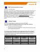
4.3.8 Standard WI-I/O 9-U2 I/O (Basic I/O) The following table shows the basic onboard I/O available in a standard WI-I/O 9-U2 module with no expansion I/O connected. For a more detailed I/O map (showing the full register range), see Appendix B: “I/O Store Registers” at the end of the manual. Address 0001 - 0008 Input / Output Description Local DIO1 – DIO8 (as Outputs) 10001 - 10008 Local DIO1 – DIO8 (as Inputs) 10009 - 10020 Setpoint status from Analog inputs 1 through 12.
parameters. Digital Inputs By selecting an Input in this display and then pressing the Edit button it will allow you to make changes to the input. Name – The inputs can be named to help with configuration or use the default, up to 30 characters including spaces. Figure 42 - Digital Inputs Debounce Time (sec) – Debounce is the time which an input must stay stable before the module decides that a change of state has occurred.
to the receiving module every 10 seconds. The receiving module will then output the pulse count over the configured update time, i.e.10 seconds Analog Inputs The Analogue Inputs have more configurable options and this is mainly due to each input also having a set point assigned to them. Analogue inputs can also be used as Voltage inputs by selection of dip switches in the WI-I/O 9-U2 modules. The WI-I/O 9-U2 Analog inputs have the following configuration parameters.
The setpoints can be controlled by using the two control options explained below. All setpoints have these controlling options. The two main setpoint control options are. Invert – This option toggles the Setpoint control logic between the default normal and inverted state. The function does not change, only the operation is inverted, e.g. if setpoint is on in its normal state, inverting the signal will mean the setpoint will be off in the normal state.
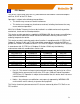
The default serial parameters of the RS485 port are 9600, N, 8, 1 which match the defaults of the WI-I/O-EX-1-S serial expansion modules. The parameters can be changed, to increase poll speeds in larger systems however the serial modules will need to match that of the WI-I/O 9-U2 RS485 port. Also if more than 3 serial expansion modules are added the “Maximum Connections” for the RS485 port on the “Serial” page will need to be adjusted.
The second is a ‘Communication OK’ which is located at register location 10020 + offset value. This register will indicate “1”when the module is communicating OK. Adding Expansion I/O to Configuration Software Select the sub branch “Expansion” under the I/O/ Branch of the module in the configuration software. Select “Add” to enter new I/O modules. Figure 48 - Expansion I/O Name - The Module can be named to help with configuration or use the default, up to 30 characters including spaces.
In Figure 51 - Failsafe Block Digital’ above, register 40501 holds an analog value that has been mapped from another module and is updated every 60 seconds. The configuration is configured so that on start-up the module will write a value of 16384 into register 40501 and then start counting down the “Fail Timeout” period , in this case it is 130 seconds which is a little over two times the update period from the sending module .
“Failsafe Blocks” above for a way of configuring a registers with a valid value at start-up 4.3.12 Sensitivity Blocks All registers have a configurable “Sensitivity” value, which determines how much the register needs to change before being sent as a “Change of State” (COS) message. All registers have a default sensitivity value of 1 except the following. The 12 analog inputs have a sensitivity of 1000 bits or approximately 3% (1000 bits from a total range of 32768 = 3.
4.3.13 Serial Configuration The WI-I/O 9-U2 has an RS-232, and an RS-485 port for serial communications. These ports are used to connect WEIDMULLER WI-I/O-EX-1-S-11, WI-I/O-EX-1-S-12 & WI-I/O-EX-1-S-13 serial expansion I/O modules. The ports can also be used to connect external Modbus RTU Master or Slave devices The port Operating Mode and the normal serial parameters, Baud Rate, Data Format, Flow Control, etc.
U2 it will need to poll the IP address of the WI-I/O 9-U2, The Port Number that is configured here and the Device ID of the serial device. Request Pause – Is the delay between serial requests in milliseconds Response Wait – Is the serial response timeout in milliseconds – a serial retry will be sent if a response is not received within this timeout. Connection Timeout – Is the TCP connection timeout in seconds – if no Modbus/TCP data is received within this timeout then the TCP connection will be dropped.
Request Pause – Is the delay between serial requests in milliseconds Response Wait – Is the serial response timeout in milliseconds – a serial retry will be sent if a response is not received within this timeout. Maximum Tries – Is the maximum number of request retries performed on the serial port. Serial - Modbus RTU Slave When configured as a Modbus RTU slave the only parameter that will need to be configured are the Date Rate, Data Format and Flow Control. 4.3.
ID” is used to determine if a Modbus transaction is to be routed to the onboard Modbus TCP Server or to a Modbus RTU device connected to the serial port. Care should therefore be taken that all serially connected Modbus devices use different Device ID’s (i.e. Modbus Slave Address) as well as being different to the onboard Device ID. Up to 32 separate connections to the Modbus TCP Server are supported. ‘Device ID’ Is the Device ID for the modules own Modbus Server/Slave.
Figure 56 - Modbus TCP Client Mapping Local Register (Master) – When the Function Code (Command) is ‘Read’ the ‘Local Register’ will be the destination register or output location on the Local device, when the Function Code (Command) is a ‘Write’ the ‘Local Register’ will be the originating register or input location on the local device.
Modbus TCP Mapping Examples Figure 57 - Modbus TCP Mapping table The first mapping in Figure 57 - Modbus TCP Mapping table above shows the Modbus Client (Master) is configured to read analog values from a device connected on the LAN. The mappings function code is “Read” and is reading a count of 4 values (Analogs) from the Ethernet address 192,168.0.17, Device ID #10, starting at address 30001, and then writing these values into its own local registers starting at 40501.
slaves over the radio network will greatly increase radio communications and is not recommended in busy systems. Modbus RTU Figure 58 - Modbus RTU Example Master Example The Modbus RTU mapping is very similar to the Modbus TCP mapping except the destination is a serial interface instead of an Ethernet address and port. The first mapping shows a read mapping from a serial device connected on the RS485 port with a Device ID of 5.
RS232/RS485 Modbus Parameters The RS232 and RS485 Modbus Parameters tabs show the configuration parameters for the RS232 and RS485 ports. These parameters are exactly the same as the serial parameters in section 4.3.13 Serial Configuration; they are displayed under the Modbus tab for convenience. Figure 60 - Modbus Parameters 4.4 Web based Configuration Some configuration options are available by web based configuration only.
Link Quality Threshold Receive Signal Strength Threshold Enable Multipath RSSI Algorithm The radio will use this threshold levels when establishing a mesh link with other radios in the system. It represents a 0-100% level of link quality (100 being the best). If the Link Quality is lower than the threshold the link will be ignored. Link Quality can be monitored on the Connectivity web page. If the link quality is lower than this threshold, then mesh routes will not be assigned over this link.
topology changes can occur that could potentially allow a shorter path to be taken, i.e. a roaming or mobile application. Without route refresh, the existing route which may not be the best or most reliable link would continue to be used. The default value is 300 seconds. Setting this parameter to zero will disable the route refresh operation which will mean the existing route will never refresh other than on module start up. Route Timeout (Sec) Save Changes and Activate.
Name Neighbour IP Register Save Changes Save Changes and Reset. Neighbour RSSI A name that describes the Neighbour (Max 32 characters). IP address of the Neighbour module you wish to monitor. IP address should be the Radio address of the WI-I/O 9-U2 Register location the RSSI value will be stored in. Save changes to non-volatile memory. The module will need to be restarted before the changes take effect. Save settings to non-volatile memory, and reboot WI-I/O 9-U2.
Netmask Interface Gateway Enabled Save Changes Save Changes and Reset. The subnet mask for the destination network. Choose the interface to use for the route. Selections are Radio, Ethernet or Any – Default is Any. Specifies the IP address of the next-hop router for the specified destination. Check this box to enable the rule. You can Uncheck the box to disable a routing rule without needing to re-enter the information at a later time. Save changes to non-volatile memory.
Signature Hopset Transmit Power Mode Data Rate Disable Rx LNA Save Changes and Reset. message that contains a unique “signature” that the radio identifies with when receiving messages. Any message with a different signature is ignored. Depending on the country this selection will be varied. USA, Australia, New Zealand and India will have a selection of 4 signatures (0, 1, 2, 3) while Europe, 5mw and 500mw models have just ‘Normal’ and ‘Compatible’.
Example #1 Figure 65 - Mesh Fixed Route#1 The Network Diagram above shows a basic network where all remote sites (2, 3 & 4) communicate back to Site #1 using Mesh Fixed Routes. Normally a meshing network will automatically learn the routes within a network and setup appropriate communication paths to the destination. In some instances it may require you to fix the radio path If a radio path is not available it will re-route its way through the mesh and locate a path.
Figure 67 - Mesh Fixed Route - Rep Site #2 The Mesh fixed Routes for Rep Site #2 are shown above. The first entry shows the communication path back to Site #1 so the Destination IP and Next Address are configured with the address 10.0.0.1 (Site #1). As Site #2 is a repeater for site #4 the second route shows the Destinations being Site #4 with a next address of Site #3.
Figure 70 – Mesh Fixed Route#2 Routing Rules The first route shows the destination and next addresses are both 10.0.0.1 as it’s a single hop. Because the destination is a Gateway on an external network the IP Gateway must be enabled. The second routing rules shows the Destination (192.168.1.100) is an external network and is outside of the radio mesh, therefore the External tick box must be enabled. The next address will be 10.0.0.1, which is the IP Gateway.
4.4.6 Module Information Web Page This Web page is primarily for information purposes. With the exception of the password, the information entered here is displayed on the home configuration webpage of the WI-I/O 9-U2. Figure 71 - Module Information Username default = “user” Password default = “user” Device Name Configuration of Username. This is the username used to access the configuration on the WI-I/O 9-U2.
4.4.7 System Tools Web page Figure 72 – System Tools System Log File Logs system instructions, etc to the screen where the log screen can be saved to a file. Not normally used, however maybe used by Technical Support to diagnose problems. The “Clear System Log” clears the log screen. Reading Configuration File Reads the module configuration into an XML file. This file can be saved by selecting “Save As” from the File menu.
Firmware Upgrade – USB (Full Firmware Upgrade) Firmware can also be upgraded using a USB flash drive with the firmware files installed. Typically a full USB upgrade is required if the existing firmware is a much older version and would requires multiple patch files to upgrade to the latest version or a patch file may not be available.
Upgrade Procedure 1. Prior to performing upgrade note the current firmware version of the WI-I/O 9U2 by connecting to the modules home webpage. This will allow you to compare this version with the final version to confirm the upgrade procedure has been performed successfully. Figure 76- firmware version 2. Remove power from WI-I/O 9-U2 if it is currently powered on, 3. Remove small Hatch Cover on right hand side of Module (If looking front on) which will reveal a USB port and switches. 4.
Product Reconfiguration Changes the operating mode between WIBMesh and WIBNet. WIBNet is a compatibility mode that will allow communications between the WI-I/O 9-U2 and earlier WEIDMULLER WI-Series Telemetry units, e.g. WI-I/O 9-X-1, 2, 3, 4, C, G, K, L, etc. Figure 79 - Product Reconfiguration The Dropdown box has two selections, Meshing Mode - Standard Weidmuller WIBMesh and is the format that the module will be in when it arrives from the factory.
4.4.8 Feature Licence Keys Web Page Allows the module to be upgraded with enhanced features or upgraded to a more advanced model .i.e. enabling the Modbus option. The Feature Licence unlock codes are purchasable by contacting Weidmuller or your local distributor. The module serial number is needed to generate the Feature Licence Key.
Chapter 5 - Diagnostics 5.1 IO Diagnostics Figure 83- I/O Diagnostics Selecting this option from the main screen will allow some basic reading and writing of the I/O store registers within the module. To read a register location, enter an address location, e.g.
5.1.1 Watchdog Error Log The module uses a number of different processes to control aspects of the internal workings of the module, i.e. Radio operation, I/O functionality, AODV communications, Modbus Communications, etc. Each process runs independent of each other and can interact with the other processes to provide a robust wireless I/O product. All processes are monitored by an internal ‘Watchdog’.
Each Expansion I/O module has the following registers. 30017 + Offset = Modbus Error Counter (number of errors the modules has had) 30018 + Offset = Last WI-I/O-EX-1-S Status Code / Modbus Error Code. Will display the following WI-I/O-EX-1-S Status Codes (Hex code 1-5 & 129), as well as the standard Modbus Response Codes shown in Appendix D with a slight difference in the code. The MSB will be one of the following bytes, 82, 84, 8F or 90 followed by the standard Modbus Response codes (01 -0B).
5.2 Connectivity (WibMesh) The Connectivity webpage displays connections and available networks. The “Connected Devices” section displays the Destination IP Address, the relaying IP Address, the number of hops the message is taking through the network, signal strength and link quality along with some message related information. The readings shown are based upon the last received data message from the device.
80 1 in 10,000 raw bit errors 60 1 in 1000 raw bit errors 40 1 in 100 20 1 in 10. Addition indications for this entry. G=Gateway, F=Fixed, E=External Flags Gateway: This unit is a gateway to provide access outside of the radio network. Fixed: Manually configured route. External: Accesses a device outside the local network.
5.3 Neighbour List (WibMesh) Figure 85 – Neighbour List Shows a current list of module IP addresses that the radio can hear. Shows the time since it was last heard from and the calculated RSSI value. This page is useful for discovering what signal levels the module has to other sites within the system including WEIDMULLER modules on different system addresses. The list will display all received radio messages, even if the message is not directly communicating to it. 5.
“Get Graph”. After the units have been running for a few minutes, and passing radio data, the graph will fill with RSSI readings across all of the radio channels in use. If the graph is approximately flat, i.e. Figure 86 - Neighbour RSSI above then there is no multipath fading between these units. If the graph shows large dips (typically one or two) across several channels, there is multipath fading between units. E.g.
5.5 Network Diagnostics (WibMesh) Figure 88 – Network Diagnostics Network Diagnostics allows you to check the communications path to other modules within the system. There are two options for checking the communications. Ping Ping is a standard Network instruction that sends out a small data probe to the IP address configured letting you know if you have a communication path or not.
Trace Route Because the modules use the AODV protocol which is a routing protocol capable of finding its own path through the network it can be difficult to determine the selected communications path. “Trace Route” allows the communications path to be traced through the network and determining how many hops the path is taking to get to the destination. Figure 89 – Trace Route The example above shows the response time from the Host to the first IP address (192.168.0.
5.6 Network Statistics (WibMesh) Figure 90– Network Statistics Period After enabling the “Gather Statistics” on the Main Network page, this page will display the average Receive and Transmit traffic throughput over a configured time period. From the drop down “Stats Period”, select the appropriate sample period then press the “Read” button.
Figure 92 – Hourly Statistics Daily and Weekly, period shows the average throughput over the daily or weekly time period. Also shows the average number of packet received (rx) and Transmitted (tx) as well as the total. Average is an estimated value based on the amount of data gathered in the time available.
5.7 Monitor Comms 5.7.1 WibMesh – Monitor Radio Comms The Monitor Radio Comms page shows radio communication frames that are received or transmitted by the radio. Figure 94 - Monitor Comms The Table below shows some data frames from the communication log screen above. Below that is another table explaining each of the field within the data frame. Corrupted data frames are shown with an “ERROR!” in the frame. Time 16:05:51.756 Tx : 911.875 16:05:51.771 Rx : 911.
Frequency Shows the Frequency of the RX/TX frame Signal Level Shows the Receive Signal Level on any received message or internal sequence number for the transmitted message.
Time Source IP Dest IP Len Type Seq 03:02:45.073629 192.168.2.146.51891 192.168.2.143.4370 7 WRITE 9 03:02:45.075693 192.168.2.143.56678 192.168.2.146.
Corrupted data frames are shown with an “ERROR!” in the frame. Time TX/RX Frequenc y Signal Level Data Lengt h 0:06:12.465 Tx : 919.125 [ 1355] ( 11) 3A 03 81 02 00 86 00 01 00 01 ... 0:06:12.545 Rx : 921.125 -56dBm ( 5) 3A 03 81 82 00 Time TX/RX Data Time stamp indicating the time from when the module was turned on.
5.8 Statistics (WibMesh & WibNet) The Statistics webpage is used for advanced debugging of WI-I/O 9-U2. This webpage details the state of the WI-I/O 9-U2 and performance information. The page is useful to WEIDMULLER technical support personnel in diagnosing problems with the module. Note that when updating the Statistics webpage, it is necessary to hold down the key while pressing the refresh button. This ensures your browsers cache is updated.
Chapter 6 - Specifications 6.1 Specifications Frequency Transmit power Transmission Modulation Receive Sensitivity Channel Spacing Radio data rate Range (LOS) Typically Antenna Connector Discrete Input Discrete Output Analog Inputs Analog Output Ethernet Port Link Activity Radio Transceiver 902–928MHz(1) ;869.525MHz, 869.
RS232 Port EIA-562 (RJ45 Connector) RS485 Port 2-Pin Terminal Block – Non-Isolated(6) Data Rate (Bps) 1200, 2400, 4800, 9600, 14400, 19200, 38400, 57600, 76800, 115200, 230400bps Serial Settings 7 / 8 Data Bits; Stop/Start/Parity (Configurable) System Address Protocols Supported User Configuration Configurable Parameters Security Protocols and Configuration ESSID; 1 – 31 Character Text String TCP/IP, UDP, HTTP, FTP, TFTP, TELNET, MODBUS RTU Master/Slave, MODBUS-TCP Client/Server All User Configura
Draw Transmit Current Draw 500mA @ 12V (1W), 250mA @ 24V (1W) Note: Specifications subject to change.
Appendix A: dBm to mW conversion table dBm to mW Conversion 110 Watts dBm Watts dBm 10 mW 10 dBm 200 mW 23 dBm 13 mW 11 dBm 316 mW 25 dBm 16 mW 12 dBm 398 mW 26 dBm 20 mW 13 dBm 500 mW 27 dBm 25 mW 14 dBm 630 mW 28 dBm 32 mW 15 dBm 800 mW 29 dBm 40 mW 16 dBm 1.0 W 30 dBm 50 mW 17 dBm 1.3 W 31 dBm 63 mW 18 dBm 1.6 W 32 dBm 80 mW 19 dBm 2.0 W 33 dBm 100 mW 20 dBm 2.5 W 34 dBm 126 mW 21 dBm 3.2 W 35 dBm 158 mW 22 dBm 4.
Appendix B: I/O Store Registers “Output Coils” 0001 0008 0009 0020 0021 0500 0501 3000 3001 10000 Local DIO1 – DIO8 as Digital Outputs. Spare Space for locally attached WI-I/O-EX-1-S Expansion I/O modules.
“Input Registers” 30001 Local AI1 – AI4. (Analog Inputs - Current Mode) 30004 AI1& AI2 - 4-20mA differential, AI3 & AI4 - 4-20mA Sink 30005 Local Supply voltage (0-40V scaling) 30006 Local 24V loop voltage (0-40V scaling) 30007 Local Battery voltage (0-40V scaling) 30008 WI-I/O-EX-1-S Supply Voltage (0-40V scaling) 30009 Local AI1 – AI4.
“Holding Registers” 40001 40002 40003 40020 40021 40500 Local AO1 & AO2 - Analog Outputs Spare Space for locally attached WI-I/O-EX-1-S Expansion I/O modules. 20 register per module address, maximum number of modules is 24 (See Appendix C: below for details) 40501 General purpose word storage area – used for: Staging area for data concentrator 42500 42501 46000 Fieldbus Mappings storage Not Available 46001 Local Pulsed Outputs 1-4. Big Endian Format.
Appendix C: Expansion I/O Registers Adding Expansion I/O modules to the WI-I/O 9-U2 will automatically add the I/O from the WI-I/O-EX-1-S modules to the internal WI-I/O 9-U2 I/O store. To calculate the register location in the I/O Store find the address of the I/O point in the tables below and add the offset. The Offset is the Modbus address multiplied by 20. E.g1. Digital input #1 on an WI-I/O-EX-1-S-11 with address 5 would be: (5x20) +10001 = 10101 E.g2.
I/O store for a WI-I/O-EX-1-S-12 Expansion I/O module 0001 + Offset DIO Outputs 1 - 8 0008 + Offset 10001 + Offset DIO Inputs 1 - 8 10008 + Offset 10019 + Offset Modbus Error indication for WI-I/O-EX-1-S module 10020 + Offset Detected indication for this WI-I/O-EX-1-S module 30001 + Offset 30008 + Offset Inputs AIN 1 – AIN8 30017 + Offset Modbus Error Counter for this WI-I/O-EX-1-S module 30018 + Offset Modbus Last Error Code for this WI-I/O-EX-1-S module. (Section 5.1.
Appendix D: Modbus Error Codes The following are Modbus Error Response codes that can be read if utilising the Modus mapping fail register and selecting a General Purpose Analog Register (30501, 40501, etc.) instead of a General Purpose Digital register (10501, 501, etc.) Dec Code 65281 65282 Hex Code FF01 FF02 Name Meaning Illegal Function The function code received in the query is not an allowable action for the server (or slave).
Specialized, use in conjunction with programming commands. 65286 FF06 Slave Device Busy 65288 FF08 Memory Parity Error The server (or slave) is engaged in processing a long– duration program command. The client (or master) should retransmit the message later when the server (or slave) is free. Specialized, use in conjunction with function codes 20 and 21 and reference type 6, to indicate that the extended file area failed to pass a consistency check.
Appendix E: Physical I/O Registers I/O Digital I/O 1 Digital I/O 2 Digital I/O 3 Digital I/O 4 Digital I/O 5 Digital I/O 6 Digital I/O 7 Digital I/O 8 Analog Input 1 (mA) Analog Input 2 (mA) Analog Input 3 (mA) Analog Input 4 (mA) Input 5 – Local V Supply Input 6 – Local +24V Analog Loop Input 7 – Local V Battery Input 8 – Local V Expansion I/O Analog Input 1 (Volts) Analog Input 2 (Volts) Analog Input 3 (Volts) Analog Input 4 (Volts) Pulse Rate 1 Pulse Rate 2 Pulse Rate 3 Pulse Rate 4 Analog 1 Setpoint Ana
Analog 12 Setpoint 10020 40001 Analog Output 1 40002 Analog Output 2 Pulsed Input 1 Count Pulsed Input 2 Count Pulsed Input 3 Count Pulsed Input 4 Count Pulsed Input 1 Rate Pulsed Input 2 Rate Pulsed Input 3 Rate Pulsed Input 4 Rate 36001-36002 36003-36004 36005-36006 36007-36008 30013 30014 30015 30016 46001-46002 Pulsed Output 1 Count 46003-46004 Pulsed Output 2 Count 46005-46006 Pulsed Output 3 Count 46007-46008 Pulsed Output 4 Count Analog Input 1 Floating Point (mA) Analog Input 2 Floating
WI-I/O-EX-1-S Serial Expansion Modules I/O Registers WI-I/O-EX-1-S-11 Description Digital I/O 1 Digital I/O 2 Digital I/O 3 Digital I/O 4 Digital I/O 5 Digital I/O 6 Digital I/O 7 Digital I/O 8 Digital I/O 9 Digital I/O 10 Digital I/O 11 Digital I/O 12 Digital I/O 13 Digital I/O 14 Digital I/O 15 Digital I/O 16 Outputs 1 Inputs 10001 Outputs 1 Inputs 10001 Outputs 1 10002 2 10002 2 10002 2 10003 3 10003 3 10003 3 10004 4 10004 4 10004 4 10005 5 10005 5 10005 5 10006 6 10006
Pulsed I/O Rate 2 Pulsed I/O Rate 3 Pulsed I/O Rate 4 Supply Voltage Analog Loop Supply 30002 30003 30004 30033 30033 30033 30034 30034 30034 All Expansion I/O is calculated by adding the ‘Offset’ to the I/O address in the table. The ‘Offset is calculated by multiplying the module address by 20, Eg.
Appendix F: GNU Free Document Licence Version 2, June 1991 Copyright (C) 1989, 1991 Free Software Foundation, Inc. 51 Franklin Street, Fifth Floor, Boston, MA 02110-1301, USA Everyone is permitted to copy and distribute verbatim copies of this license document, but changing it is not allowed. Preamble The licenses for most software are designed to take away your freedom to share and change it.
that there is no warranty (or else, saying that you provide a warranty) and that users may redistribute the program under these conditions, and telling the user how to view a copy of this License. (Exception: if the Program itself is interactive but does not normally print such an announcement, your work based on the Program is not required to print an announcement.) These requirements apply to the modified work as a whole.
8. If the distribution and/or use of the Program is restricted in certain countries either by patents or by copyrighted interfaces, the original copyright holder who places the Program under this License may add an explicit geographical distribution limitation excluding those countries, so that distribution is permitted only in or among countries not thus excluded. In such case, this License incorporates the limitation as if written in the body of this License. 9.
Weidmuller USA Corporate Headquarters 821 Southlake Boulevard Richmond, Virginia 23236 Main: 804.794.2877 Customer & Technical Support: 1 800.849.9343 Fax: 804.794.0252 info@weidmuller.com / support@weidmuller.com www.weidmuller.com Weidmuller Canada Corporate Headquarters 10 Spy Court Markham, Ontario L3R 5H6 Main: 905.475.1507 Toll Free: 1 800.268.4080 Toll Free Fax: 1 877.300.5635 Fax Admin: 905.475.5855 info1@weidmuller.ca / support@weidmuller.ca www.weidmuller.