User Manual WI-I/O 9-x Wireless Module WI-I/O-EX-1-S-x Serial Module Weidmuller Inc.
WI-I/O 9-x Wireless Module WI-I/O-EX-1-S-x Serial Module User Manual v2.16 Thank you for your selection of the WI-I/O-9-x WI-I/O-EX-1-S-x module for your I/O needs. We trust it will give you many years of valuable service. ATTENTION! Incorrect termination of supply wires may cause internal damage and will void warranty. To ensure this product enjoys a long life, double check ALL your connections with the user’s manual before turning the power on.
Contents FCC Notice: WI-I/O 9-x Wireless I/O Module This user’s manual is for the Weidmuller, Inc. WI-I/O 9-x wireless I/O module. This device complies with Part 15.247 of the FCC Rules. Operation is subject to the following two conditions: 1) This device may not cause harmful interference and 2) This device must accept any interference received, including interference that may cause undesired operation. This device must be operated as supplied by Weidmuller, Inc.
WI-I/O 9-x Wireless Module WI-I/O-EX-1-S-x Serial Module User Manual v2.16 Important Notice Weidmuller, Inc. products are designed to be used in industrial environments, by experienced industrial engineering personnel with adequate knowledge of safety design considerations. Weidmuller, Inc. radio products are used on unprotected license-free radio bands with radio noise and interference.
Contents Limited Lifetime Warranty, Disclaimer and Limitation of Remedies Weidmuller, Inc. products are warranted to be free from manufacturing defects for the “serviceable lifetime” of the product. The “serviceable lifetime” is limited to the availability of electronic components. If the serviceable life is reached in less than three years following the original purchase from Weidmuller, Inc., Weidmuller, Inc. will replace the product with an equivalent product if an equivalent product is available.
WI-I/O 9-x Wireless Module WI-I/O-EX-1-S-x Serial Module User Manual v2.16 CONTENTS CHAPTER ONE 1.1 INTRODUCTION ..................................................................................................8 GENERAL ....................................................................................................................................8 CHAPTER TWO INSTALLATION.................................................................................................11 2.1 GENERAL ..............
Contents 3.2.5 Indicating a Communications Problem............................................................................35 3.2.6 Testing and Commissioning.............................................................................................36 3.3 SECURITY CONSIDERATIONS ....................................................................................................36 CHAPTER FOUR CONFIGURATION ...........................................................................................38 4.
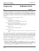
WI-I/O 9-x Wireless Module WI-I/O-EX-1-S-x Serial Module Chapter One User Manual v2.16 INTRODUCTION 1.1 General The WI-I/O 9-x & WI-I/O-EX-1-S-x range of I/O modules has been designed to provide standard “offthe-shelf” telemetry functions, for an economical price. Telemetry is the transmission of signals over a long distance via a medium such as radio or twisted-pair wire. Although the WI-I/O 9-x_WI-I/O-EX-1S-x is intended to be simple in its application, it also provides many sophisticated features.
• WI-I/O-EX-1-S-11, WI-I/O-EX-1-S-12 and WI-I/O-EX-1-S-13 modules have only serial communications. All other specifications are as per the WI-I/O 9-1, 2, 3 & 4 modules. The WI-I/OEX-1-S-x modules are compatible with WI-I/O 9-x modules. WI-I/O-EX-1-S-x modules may be used for serial I/O applications, or as I/O expansion for WI-I/O 9-x modules. • The WI-GTWY-9-xxx modules provides an interface between host devices such as PLC’s or SCADA computers, and a wireless I/O system comprising WI-I/O 9-x modules.
WI-I/O 9-x Wireless Module WI-I/O-EX-1-S-x Serial Module User Manual v2.16 Input signals connected to a module are transmitted to another module and appear as output signals. These input signals may also be configured to appear as “inverted” signals on the output. A transmission occurs whenever a "change-of-state" occurs on an input signal. A "change-of-state" of a digital or digital internal input is a change from "off" to "on" or vice-versa.
Chapter Two INSTALLATION 2.1 General The WI-I/O 9-x_WI-I/O-EX-1-S-x module is housed in a rugged aluminium case, suitable for DIN-rail mounting. Terminals are suitable for cables up to 2.5 sqmm in size. All connections to the module should be SELV only. Normal 110/220/240V mains supply should not be connected to any input terminal of the module. Refer to Section 2.3 Power Supply.
WI-I/O 9-x Wireless Module WI-I/O-EX-1-S-x Serial Module User Manual v2.16 Line-of-sight paths are only necessary to obtain the maximum range. Obstructions will reduce the range however, but may not prevent a reliable path. A larger amount of obstruction can be tolerated for shorter distances. For very short distances, it is possible to mount the antennas inside buildings. An obstructed path requires testing to determine if the path will be reliable (refer the section 6 of this manual).
Cable type RG58 Loss (dB per 30 ft / 10 m) -5 RG213 -2.5 Cellfoil -3 The net gain of the antenna/cable configuration is determined by adding the antenna gain and the cable loss. For example, a 6 element Yagi with 70 feet (20 metres) of Cellfoil has a net gain of 4dB (10dB – 6dB). Connections between the antenna and coaxial cable should be carefully taped to prevent ingress of moisture.
WI-I/O 9-x Wireless Module WI-I/O-EX-1-S-x Serial Module User Manual v2.16 The Yagi gain also acts on the receiver, so adding Yagi antennas at both ends of a link provides a double improvement. Yagi antennas are directional. That is, they have positive gain to the front of the antenna, but negative gain in other directions. Hence Yagi antennas should be installed with the central beam horizontal and must be pointed exactly in the direction of transmission to benefit from the gain of the antenna.
2.3 Power Supply The WI-I/O 9-x_WI-I/O-EX-1-S-x power supply is a switch-mode design which will accept either AC or DC supply. The module may also be powered from a solar panel without an external solar regulator. The module accepts supply voltages in the following ranges : 12 - 24 volts AC RMS or 15 - 30 volts DC at the “supply” terminals, or 11.5 -15 volts DC at the “battery” terminals. The power supply should be rated at 1.5 Amps and be CSA Certified Class 2.
WI-I/O 9-x Wireless Module WI-I/O-EX-1-S-x Serial Module Power Supply DC Out + _ User Manual v2.16 SUP1 BAT+ SUP2 GND GND 15 – 30 VDC SOL >17V if battery is used - WI-I/O 9 + Optional Battery Fuse 2A The module may also be powered from an external 11.5 - 15 VDC battery supply without the need for a "normal" supply connected to "SUP1". This external battery supply is connected to "BAT+" and "GND" terminals. The positive lead of the external supply should be protected by a 2A fuse.
The analog loop load is the total signal current for the AI’s and AO’s which are powered from the internal 24V supply. Externally powered loops are not included in this. Solar Panel _ SUP1 BAT+ SUP2 GND GND SOL + - WI-I/O 9 + Solar Battery Fuse 2A The solar panel is connected to the "SOL" (positive) and "GND" (negative) terminals and the battery connected to the "BAT+" (positive) and "GND" (negative) terminals.
WI-I/O 9-x Wireless Module WI-I/O-EX-1-S-x Serial Module User Manual v2.16 TYPE OF LOAD LOAD mA WI-I/O 9-1 quiescent 85 WI-I/O-EX-1-S-1 quiescent 45 6 DI @ 10 mA 60 3 AI @ 20mA x 2 120 4 DO @ 25mA 100 Battery charging 100 TOTAL 510 So both modules could be powered from one power supply and one battery, provided the external supply voltage is more than 15VAC or 17VDC. 2.3.
Voltage-free contact input Transistor input DI 1 DI 4 + _ COM V+ V- WI-I/O 9 For pulse inputs, refer to Section 2.4.6. 2.4.2 Digital Outputs (WI-I/O 9-1) The ”-1” module provides four normally open voltage-free relay contacts, rated at AC 50V/5A, DC 30V/2A, 20V/5A. These outputs may be used to directly control low-powered equipment, or to power larger relays for higher powered equipment. When driving inductive loads such as AC relays, good installation should include capacitors (e.g.
WI-I/O 9-x Wireless Module WI-I/O-EX-1-S-x Serial Module User Manual v2.16 DO 1 DC Load DO 2 WI-I/O 9 COM + _ Max 30VDC 0.5A Digital outputs may be configured to individually turn off if no command message is received to that output for a certain period. This feature provides an intelligent watch dog for each output, so that a communications failure at a transmitting site causes the output to revert to a known state. See Chapter 4 Configuration for further details.
1+" or "AI 2+", etc) should be connected to "+24V". Externally powered loops may be connected by connecting the input between "AI 1+" and “AI 1-” for analog input 1 or "AI 2+" and “AI 2-” for analog input 2, and so on for other inputs. Common mode voltage may be -0.5V to 27V. Shielded cable is recommended for analog I/O loops to minimise induced noise and Radio Frequency Interference (RFI). The shield of the cable should be connected to earth at one of the cable only.
WI-I/O 9-x Wireless Module WI-I/O-EX-1-S-x Serial Module User Manual v2.16 signals. If connecting to an external device such as an electronic indicator, recorder or PLC / DCS input, the loop can be powered by either the WI-I/O 9-x or the device. Externally powered loops to 27 VDC may be connected by connecting the output between the "AO” terminal (positive) and the "COM" terminal (negative).
2.4.6 Pulse Input (WI-I/O 9-1) For the ”-1” module, digital input 1 may be configured as a pulse input (max rate 100 Hz, min. off time 5 ms). In this mode, both the pulse rate and the pulse count are available for mapping to a remote output. The pulse rate may appear at any analog output on the remote unit, while the pulse count can appear at a Pulse Output on another ”-1” or Digital/Pulse Output on a ”-3” or “-4” unit. The pulse input should be connected in the same way as a digital input.
WI-I/O 9-x Wireless Module WI-I/O-EX-1-S-x Serial Module 2.4.8 User Manual v2.16 Pulse Output (WI-I/O 9-1) A single FET output to common rated at 30VDC, 500 mA is provide for the pulse output "PO". This output accurately recreates the pulses counted at a pulse input at another module. +24V PO WI-I/O 9 Use by-pass diode if counter is inductive.
2.4.10 RS232 Serial Port The serial port is a 9 pin DB9 female and provides for connection to a terminal or to a PC for configuration, field testing and for factory testing. This port is internally shared with the RS485 ensure that the RS485 is disconnected before attempting to use the RS232 port. Communication is via standard RS-232 signals. The WI-I/O 9-x_WI-I/O-EX-1-S-x is configured as DCE equipment with the pin-out detailed below.
WI-I/O 9-x Wireless Module WI-I/O-EX-1-S-x Serial Module User Manual v2.16 The modules include a terminating resistor on-board. If the WI-I/O 9-x module is the first or last module in the RS485 chain, then the terminating resistor may be connected by operating the single DIP switch in the end-plate next to the RS485 terminals. “On” or “down” means that the resistor is connected.
Chapter Three 3.1 OPERATION Power-up and Normal Operation When power is initially connected to the module, the module will perform internal diagnostics to check its functions. The following table details the status of the indicating LED’s on the front panel under normal operating conditions.
WI-I/O 9-x Wireless Module WI-I/O-EX-1-S-x Serial Module User Manual v2.16 module is not already transmitting - if there is another transmission, the WI-I/O 9-x will wait until the transmission is complete. When the WI-I/O 9-x transmits, it will wait for a return “acknowledgement” message from the destination module, indicating a successful message. If transmissions are not successful (radio or serial), then the module will re-try up to four times at random intervals to transmit the message.
remote module every ten minutes. For critical applications, the “comms fail” status can be configured to be reflected to an output on the module for alert purposes. The outputs on the module may also be configured to reset after a specified timeout (digital outputs reset to “off”, analog outputs reset to 0 mA) allowing the system to turn off in a controlled manner e.g. a pump will never be left running because of a system failure.
WI-I/O 9-x Wireless Module WI-I/O-EX-1-S-x Serial Module User Manual v2.16 transmissions increase the accuracy of the output and give extra system reliability. Analog Change-of-state A "change-of-state" for an analog input, battery voltage or pulse input rate is a change in value of the signal of 3% (configurable) since the last transmission. Note that the sensitivity of 3% refers to 3% of the analog range, not 3% of the instantaneous analog value. That is, if an analog input changes from 64% (14.
In general, the following may be used as a rule of thumb for calculating the appropriate sensitivity required for a given application: Instantaneous change of 2 x sensitivity on input → 3 second output response Instantaneous change of 10 x sensitivity on input → 5 second output response The analog inputs have 15 bit resolution and 0.016mA accuracy. Pulse input change of state Pulse input counts do not use “change-of-state” transmissions.
WI-I/O 9-x Wireless Module WI-I/O-EX-1-S-x Serial Module User Manual v2.16 changed by the user. The pulse output update time should not be set to be more than the pulse input update time. Note that the maximum pulse rate for both inputs and outputs is 100Hz. As well as accumulating the pulse input, the module will also calculate the rate of pulses. Pulse rates are treated as an “internal” analog input and are configured with analog sensitivities for change-of-state transmissions.
after the first repeater, then the source module CF status will not set. To indicate comms status on this type of link, the “Reset Output” function should be used. 3.1.6 Resetting Outputs Each digital and analog output may be individually configured to reset if that output has not received a change-of-state or an update message within a certain time period. Generally this time is set to twice the update period, so at least one update can be missed before an output is reset.
WI-I/O 9-x Wireless Module WI-I/O-EX-1-S-x Serial Module User Manual v2.16 radio paths will require re-try transmissions and will reduce the peak channel density. If there are other users on the radio channel, then this peak figure will also decrease. Dual Band Operation The WI-I/O 9-x radio band is split into two sub-bands, 902-915 MHz and 915 – 928 MHz . In America and Canada, the WI-I/O 9-x uses both sub-bands - but in other countries, only the high sub-band.
3.2.4 Design for Failures All well designed systems consider system failure. I/O systems operating on a wire link will fail eventually, and a radio system is the same. Failures could be short-term (interference on the radio channel or power supply failure) or long-term (equipment failure). The modules provide the following features for system failure :• Outputs can reset if they do not receive a message within a configured time.
WI-I/O 9-x Wireless Module WI-I/O-EX-1-S-x Serial Module User Manual v2.16 Fail-to-receive alarm. The second method is to set up a “comms OK” output using the “Reset Outputs” function. The output is normally on, indicating “comms OK”, and will reset if the module does not receive a message from the remote module within the configured reset time. Consider a link between module #1 and #2, and assume that you want a “comms OK” output at #1.
modules use frequency encoding and a very secure addressing system to ensure this does not occur. An additional security level using data encryption can also be selected. 3. Malicious operation, or “hacking” This is the problem most associated with security concerns - the ability for someone to access information from a radio system by “listening-in”, or to cause damage by transmitting radio messages to force outputs. A security option can be selected during the module configuration to protect against this.
WI-I/O 9-x Wireless Module WI-I/O-EX-1-S-x Serial Module Chapter Four User Manual v2.16 CONFIGURATION 4.1 Introduction The modules are configured by connecting a computer (PC) using the Configuration Software program. The same software program is used to configure WI-I/O 9-x and WI-GTWY-9-xxx modules - for more information, refer to the separate User Manuals for these products. Each module is configured with a system address and a unit address.
In addition to these network configurations, operational parameters called User Options may be configured to change the features of the operation. 4.2 Easy Configuration Using Default Settings If your application requires only a single pair of modules, communicating via radio or serial link, default settings may satisfy your needs. If so, no configuration is required. Essentially, all inputs at Module A are reflected at the corresponding outputs at Module B.
WI-I/O 9-x Wireless Module WI-I/O-EX-1-S-x Serial Module User Manual v2.16 For “-2” and “-3” modules, the default configuration is as follows :- Note that there is no default configuration for the “-4” modules.
4.3 Configuration Software This chapter describes installation and operation of configuration software for the radio and serial telemetry modules. The configuration software runs on a conventional PC as a Windows application. The software creates a configuration file which can be loaded into a module via RS232. The configuration software also allows the configuration of a module to be loaded for display and modification. Configuration files are created and stored in project directories.
WI-I/O 9-x Wireless Module WI-I/O-EX-1-S-x Serial Module 4.3.2 User Manual v2.16 Program Operation Start the software by either clicking on the start bar and navigating to the Configuration menu or by running WISeries.exe in the directory selected in the setup stage. The Initial screen will appear. The configuration is performed for a complete system.
to view the configuration details but you cannot make changes. The password can be between 6 and 256 characters. You can also change password by selecting this option from the “Utilities” menu. If you are starting a new project, you have the option of “Enabling Security” - please read Section 4.3.7 and the associated warnings before using this option. To proceed with the configuration, double-click on the project name on the menu on the left side of the screen. “Units” will appear.
WI-I/O 9-x Wireless Module WI-I/O-EX-1-S-x Serial Module User Manual v2.16 Configuring an individual module Double-click on a unit shown on the left-han d menu. The configuration options for each unit will appear. We recommend that you configure I/O mappings first, and then other options. Select “Mappings” and the following screen appears.
I/O Mapping To enter an I/O mapping, select “New I/O Mapping”. 1. The I/O mapping display will show all inputs at the selected module - both physical inputs and internal inputs. Select the input to be mapped. 2. If you wish to invert the mapping, select the “Invert Input” box. If you invert an input, then the output will be the reverse of the input. Analog I/O can also be reversed - 4mA will be 20mA etc. Do not invert pulse inputs. 3.
WI-I/O 9-x Wireless Module WI-I/O-EX-1-S-x Serial Module WI-I/O 9-1 WI-I/O 9-2 User Manual v2.
To delete an existing mapping To delete a mapping, select the mapping and delete or right-mouse click and select Delete. Configuring Start-Up Polls When a unit is first turned on, its outputs will not be set until it receives update messages from other units in the system. To that outputs are set as soon as possible after start-up the unit may be configured to “Poll” any other units with mapping s to its o utputs. Select the remote unit to be polled from the unit list, or enter the unit address in the box.
WI-I/O 9-x Wireless Module WI-I/O-EX-1-S-x Serial Module User Manual v2.16 DO1 each time communications to unit 12 is not successful. If DO1 has a “Reset output” time of 10 minutes configured for DO1, then DO1 will reset (de-activate) 10 minutes after the last comms fail to unit 12. Debounce Configuration Debounce is the time which an input must stay stable before the module decides that a change of state has occurred.
in special circumstances. It is important to remember the principle - “Less radio traffic means better communications”. Frequent updates from multiple units causes congestion of the radio channel, which results in increased communication failures and poorer performance of the system. To change an update time, select “Update Times” on the left-hand menu and double-click the selected input. The update time will be shown in days:hours:minutes:seconds. Change the values in each field.
WI-I/O 9-x Wireless Module WI-I/O-EX-1-S-x Serial Module User Manual v2.16 Analog Sensitivity Configuration The analog sensitivity is the change required in an analog input before a “Change Of State” is detected, and the new analog value is transmitted. For input signals which vary widely over a short period of time or have a normal oscillation, the analog sensitivity should be set to an appropriately large value. This ensures that many change messages are not transmitted in too short a time.
Pulse Input Count Configuration PI1 of the -2 and -4 modules normally count up to 100Hz (as for the other PI’s), however can be configured to count up to 1000Hz. This configuration actually divides the input count by 10 - each count in the PI1 register is then equivalent to 10 input pulses. If PI1 is mapped to a PO, then the maximum output pulse rate is 100Hz, however each output pulse is equivalent to 10 input pulses.
WI-I/O 9-x Wireless Module WI-I/O-EX-1-S-x Serial Module User Manual v2.16 Pulse Output Update Time Configuration The pulse output update time is the time period over which pulses are output after a PI update is received. It should be configured to correspond to the pulse input update time for the corresponding pulse input. This ensures that the pulse output rate matches as closely as possible the pulse input rate which it is reflecting.
4.3.3 Programming Configurations to Modules To program a module : • Connect the cable from the PC’s serial port to the module serial port (see 2.4.10 for cable connections) • From the Utilities menu, select “Serial Port Setup” • Select the appropriate serial port (COM1 COM4) • Select the unit to be configured from the left-hand menu • Double-click “Program Unit”. Each module will need to be programmed individually. 4.3.
WI-I/O 9-x Wireless Module WI-I/O-EX-1-S-x Serial Module User Manual v2.16 recommend that all system additions and changes be made to the archived configuration files first, and then downloaded to the module/s. This ensures that the archived files are always maintained and accurate. If you modify the configuration of a module by uploading and then downloading, then the module configuration will be different then the archived files.
over-written. • You can change the security key in the configuration files simply by entering a new security key in the security key window. You will be prompted to confirm the new security key. If the configuration files are password-protected, you will be asked for the password. Note that if you change the security key, it will not match the security key previously loaded into existing modules.
WI-I/O 9-x Wireless Module WI-I/O-EX-1-S-x Serial Module User Manual v2.16 If you wish to change the security key, simply enter a new key in the configuration program, and download the new configuration to all modules in the system. 4.3.8 Using WI-I/O-EX-1-S-x Modules WI-I/O-EX-1-S-x modules can be used by themselves, as “line telemetry” or “wired I/O”, or they can be used as I/O expansion for WI-I/O 9-x modules.
Example 2 - Mapping to a remote WI-I/O 9-x. In this example, a WI-I/O-EX-1-S-x-2 is connected to WI-I/O 9-1#8. DI1 is mapped to a remote WIGTWY-9-MD1 module. The WI-I/O 9-x that is connected to the WI-I/O-EX-1-S-x module acts as a repeater - a serial-to-radio repeater. When DI1 changes, the WI-I/O-EX-1-S-x will send a message via the serial link to WI-I/O 9-1#8. WI-I/O 9-x_WI-I/O-EX-1-S-x 2.
WI-I/O 9-x Wireless Module WI-I/O-EX-1-S-x Serial Module User Manual v2.16 Example 3 - Mapping to another WI-I/O-EX-1-S-x which is connected to a different WI-I/O 9-x In this example, both WI-I/O 9-x modules act as repeaters. The first is a “serial-to-radio” repeater and the second is a “radio-to-serial” repeater.
Chapter Five General WI-I/O 9-x Radio standards Housing SPECIFICATIONS FCC Part 15A, Part 15.247 902 – 928 MHz, 1W 130 x 185 x 60mm DIN rail mount Refer section 5.1 dimensioned drawing Powder-coated, extruded aluminium for Suitable for 2.
WI-I/O 9-x Wireless Module WI-I/O-EX-1-S-x Serial Module User Manual v2.
S-3 None WI-I/O 9-x_WI-I/O-EX-1S-4 Four plus 12 selectable I/O Digital Outputs Digital Outputs WI-I/O 9-1_WI-I/O-EX-1- Relay output contacts, normally open, AC 5A 50V S-1 Four DC 2A 30V, 5A 20V WI-I/O 9-2_WI-I/O-EX-1S-2 One WI-I/O 9-3_WI-I/O-EX-1S-3 Eight WI-I/O 9-4_WI-I/O-EX-1S-4 Four plus 12 selectable I/O Pulse Inputs WI-I/O 9-1_WI-I/O-EX-1- Uses DI1. Max rate 100Hz, min. off-time S-1 One 5msec. Uses DI1-4. Max rate of DI1 is 1000Hz, min. off-time 0.
WI-I/O 9-x Wireless Module WI-I/O-EX-1-S-x Serial Module User Manual v2.16 Analog Input Setpoints WI-I/O 9-1_WI-I/O-EX-1- Configurable high & low set-points, allowing S-1 AI 1 only set/reset of remote digital outputs WI-I/O 9-2_WI-I/O-EX-1S-2 AI 1-4 Analog Outputs current sink to common max loop voltage 27V, WI-I/O 9-1_WI-I/O-EX-1- Resolution 15 bit, Accuracy 0.1% S-1 Two 4-20mA Resolution 12 bit, Accuracy 0.
Chapter Six TROUBLESHOOTING 6.
WI-I/O 9-x Wireless Module WI-I/O-EX-1-S-x Serial Module User Manual v2.16 6.2 6.2.1 Self Test Functions Input to Output Reflection (WI-I/O 9-1_WI-I/O-EX-1-S-1 only) The unit will require re-configuration after SELF TEST. Ensure you know the required operational configuration including system and unit addresses so that the network can be restored after testing. Remove the cover in the front panel, and set the DIP switches as shown below.
functions. Use of the diagnostics menu does not affect module configuration. The diagnostics functions can be accessed from the E Series Config software - the same software package used to configure the modules. Connect the laptop or PC to the module using a configuration RS232 cable. Either open the archived project containing the module, or start a New Project and select “Load a New Unit” - select the correct type of module. After the unit has loaded, select the Diagnostics box.
WI-I/O 9-x Wireless Module WI-I/O-EX-1-S-x Serial Module User Manual v2.16 Connect the module (ensure the RS485 port is disconnected first) to the PC using the same serial cable used for configuration. The diagnostics menu is accessed by removing the blue “plug” from the front of the module and setting all switches to ‘0’ or “Open”, and holding down the red button for approximately 5 seconds, until the RX LED lights continuously.
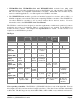
WI-I/O 9-1/WI-I/O-EX-1-S-1 Modules 1234MLS P CNT AI1 AI2 0101001 00F6 C000 4000 PRATE VBATT 8000 9C00 The first 7 values (1234MLS) each represent a single digital input. A ‘1’ indicates that that input is ON, and a ‘0’ indicates that the corresponding input is OFF. "1234" represents the four physical digital inputs, DI1 to DI4. "M" is the mains fail status (‘1’ for mains fail, ‘0’ for mains OK). "L" is the battery low volts status (‘1’ for low volts ‘0’ for OK). "S" is the set-point status.
WI-I/O 9-x Wireless Module WI-I/O-EX-1-S-x Serial Module User Manual v2.16 VBATT is the current internally derived battery voltage. 4000 corresponds to 8 Volts, C000 represents 16 volts. A quicker method is use the calculation : Battery voltage (volts) = ½ I + 6, where I is the mA value determined from the above table using VBATT. For example, a value of VBATT of A000 gives an I value of 16mA from the above table. The battery voltage corresponding to this is 14V (or ½ x 16 + 6).
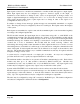
Transmitted messages are displayed starting in the leftmost column of the display. Received messages are displayed with the received signal strength preceding the message. The first four hexadecimal digits are the system address attached to the message, and must match for units to communicate successfully. The received signal strength is in negative dBm - the lower the measurement, the stronger the radio signal. A measurement larger than 95 indicates a weak radio signal.
WI-I/O 9-x Wireless Module WI-I/O-EX-1-S-x Serial Module Displayed Switches 1 1 1 0 User Manual v2.16 0 0 1 0 1110001001010101 0 1 0 1 0 1 0 1 Signal This option provides for testing the radio path between two units for a suitable reliability margin. Although a pair of units may communicate successfully, radio communication may be affected by a range of influences, including atmospheric conditions, changing landscape, degradation of antennas or co-axial cable, low battery voltage etc.
indication while adjusting the orientation of the antenna. A peak in signal level indicates optimum orientation of the antenna. 6.2.4 Comms Logging These options allow logging and display of radio communications. To start “Comms logging”: • select option the “Comms” option from the diagnostics menu (see section 6.2.3), • select ‘Stop Terminal’ and then • select ‘Start Comms’. The display will show radio messages transmitted and received.
WI-I/O 9-x Wireless Module WI-I/O-EX-1-S-x Serial Module User Manual v2.16 channel and value. You can display the register values in Decimal by selecting “Dec” at the bottom of the screen. If you select “Dig”, the values will be displayed as a 0 or 1 digital value (1 if the 16-bit value is greater than 50% - that is, the most significant bit is 1). If you select “Anlg”, the value will be displayed as a 420mA range. To stop “comms logging”, select the “Stop Comms” box.
6.3 Radio Path Testing To carry out a radio path test, you will need two WI-I/O 9-x modules. One module will be “fixed” and the other “mobile”. Both units will need power supplies and antennas. The power supply for the mobile unit is normally a 12V battery, but make sure that the battery is fully charged - batteries with low voltage will lead to low radio power which will affect the test result. The object of the test is to determine whether radio paths are reliable, marginal or unreliable.
WI-I/O 9-x Wireless Module WI-I/O-EX-1-S-x Serial Module User Manual v2.16 measurement is likely to “jump around” or oscillate, to determine an average measurement. Now operate the switch several times - take the average measurement of the signal transmitted from the fixed unit. The radio path is reliable if the transmitted signal is 10dB above the noise level, or better than – 98dBm. For example, if the noise level is –115dBm, then the minimum level for reliability is – 98dBm.
Chapter Seven WARRANTY & SERVICE We are pleased that you have purchased this product. Weidmuller, Inc. products are warranted to be free from manufacturing defects for the “serviceable lifetime” of the product. The “serviceable lifetime” is limited to the availability of electronic components. If the serviceable life is reached in less than three years following the original purchase from Weidmuller, Inc., Weidmuller, Inc.
WI-I/O 9-x Wireless Module WI-I/O-EX-1-S-x Serial Module Appendix A User Manual v2.16 SYSTEM EXAMPLE The following example of a system is a comprehensive guide to using some of the features of the range and design of system. The example application is a pump station which supplies water from a reservoir to a tank station.
The following design points should be noted :• A test of the radio path between the pump station and the tank station indicated that the radio path would be reliable provided antennas were installed at 6 m above the ground. At each site, the coaxial cable would be approx 30 feet in length, so it was decided to use 6 element Yagi antennas with RG58 coaxial cable - the Yagi antennas would compensate for the loss in the cable.
WI-I/O 9-x Wireless Module WI-I/O-EX-1-S-x Serial Module Tank Station Configuration The WI-I/O 9-2 module has the following configuration :- Note the following points in the configuration: • #1 is a repeater for communications between #2 and #94 • The pulse rate scaling for PIN1 has been set to 5 Hz to match the maximum flow rate of the flow meter. Note that PIN1 has not been configured for "divide by 10" (for 1000 Hz pulse signals). • AIN1 (the level transducer) is mapped to AO1 at the WI-I/O 9-3.
concern of wave action on the surface of the tank causing un-necessary change transmissions. This debounce time will also operate on the Pulse Rate value, but as the flow rate changes slowly, this will not affect the performance of this signal. • SETPOINT1 (the set-point status for AI1) is mapped to DO2 of #1 (pump station). The set-point values for this setpoint have been set to 40% and 75%. When the tank level drops to 40%, DO2 at the pump station will activate to start the pump.
WI-I/O 9-x Wireless Module WI-I/O-EX-1-S-x Serial Module User Manual v2.16 Note the following points in the configuration: • Note that no repeater address is necessary between #1 and #94. • DIN2 (pump running signal) has two mappings - a mapping to DO1 at #2 (tank station) and DO2 at #94 (control station). When DIN2 changes, there will be two separate change messages transmitted - one by radio to #2 and one by serial link to #96. • AIN1 (pump amps) is mapped to AO3 at #94 (control station).
• The only mappings are Start-up polls. Note that there are two separate polls, one for each remote module. • PO 3 has been configured as a PO. Its pulse output update time is the same as the PI update time at the remote module (both have been left at their default value of 1 minute). • Reset times have been selected for the analog outputs (21 minutes) but not the digital outputs.
WI-I/O 9-x Wireless Module WI-I/O-EX-1-S-x Serial Module User Manual v2.
COM +24V DOT AI 6+ AI 5+ AI 4+ COM AI 3+ GND BAT+ WIRING DRAWING - WI-I/O 9-2 WI-I/O-EX-1-S-2 OUTPUT WI-I/O-EX-1-S-2 INPUTS - +AI 2 - +AI 1 4 +24V DI 4 COM 3 DI 3 DI 1 SOL GND SUP1 SUP2 WI-I/O 9-x_WI-I/O-EX-1-S-x 2.
WI-I/O 9-x Wireless Module WI-I/O-EX-1-S-x Serial Module User Manual v2.
DIO12 DIO11 DIO9 OUTPUTS DIO10 DIO8 DIO7 COM DO 4 DO 3 DO 2 DO 1 SOL GND BAT+ WIRING DRAWING -WI-I/O 9-4, WI-I/O-EX-1-S-4 I/0 WI-I/O-EX-1-S-4 DIO6 DIO5 DIO4 DIO3 DIO2 DIO1 COM I/0 DI 4 DI 3 DI 2 DI 1 GND SUP1 WI-I/O 9-x_WI-I/O-EX-1-S-x 2.