
Manual

WI-I/O 9-x Wireless Module User Manual v2.16
WI-I/O-EX-1-S-x Serial Module
Page 12
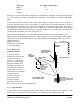
Line-of-sight paths are only necessary to obtain the maximum range. Obstructions will reduce the
range however, but may not prevent a reliable path. A larger amount of obstruction can be tolerated for
shorter distances. For very short distances, it is possible to mount the antennas inside buildings. An
obstructed path requires testing to determine if the path will be reliable (refer the section 6 of this
manual).
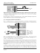
Where it is not possible to achieve reliable communications between two modules, then a third module
may be used to receive the message and re-transmit it. This module is referred to as a repeater. This
module may also have input/output (I/O) signals connected to it and form part of the I/O network - refer
to Chapter 4 Configuration of this manual.
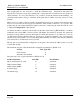
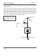
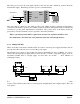
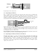
An antenna should be connected to the module via 50 ohm coaxial cable (eg RG58, RG213 or Cellfoil)
terminated with a male SMA coaxial connector. The higher the antenna is mounted, the greater the
transmission range will be, however as the length of coaxial cable increases so do cable losses. For use
on unlicensed frequency channels, there are several types of antennas suitable for use. It is important
antenna are chosen carefully to avoid contravening the maximum power limit on the unlicensed channel
(if in doubt refer to an authorised service provider).
The net gain of an antenna/cable configuration is the gain of the antenna (in dBi) less the loss in the
coaxial cable (in dB).
The maximum net gain of the antenna/cable configuration permitted for WI-I/O 9-x is
Country Max. gain (dB)
USA / Canada 6
Australia / New Zealand 0
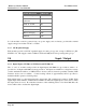
The gains and losses of typical antennas for WI-I/O 9-x are
Standard Antennas Gain (dB) Part Numbers
Dipole with integral 15’ cable 0 6720005080
5dBi Collinear (3dBd) 5 6720005081
8dBi Collinear (6dBd) 8 6720005082
6 element Yagi 10 6720005084
16 element Yagi 15 6720005085