
Manual

WI-I/O 9-x_WI-I/O-EX-1-S-x 2.16 Page 21
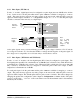
1+" or "AI 2+", etc) should be connected to "+24V".
Externally powered loops may be connected by connecting the input between "AI 1+" and “AI 1-” for
analog input 1 or "AI 2+" and “AI 2-” for analog input 2, and so on for other inputs. Common mode
voltage may be -0.5V to 27V.
Shielded cable is recommended for analog I/O loops to minimise induced noise and Radio Frequency
Interference (RFI). The shield of the cable should be connected to earth at one of the cable only. The
use of shielded wiring inside an enclosure containing a module is also recommended.
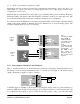
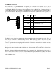
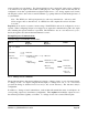
To connect an AI on the WI-I/O 9-x to an analog signal from a PLC or DCS output, check the internal
circuit of the output carefully as different devices use different ways to create an analog signal. The
following diagram shows two ways of connecting.
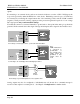
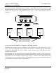
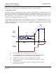
2.4.5 Analog Outputs (WI-I/O 9-1 and WI-I/O 9-3)
The ”-1” module provides two 4 - 20 mA DC analog outputs for connecting to instrument indicators for
the display of remote analog measurements. The ”-3” module provides eight 0 - 20 mA DC analog
outputs. Each analog output is a "sink" to common.
A 24VDC supply is available on the module for powering the analog output loop (max external loop
resistance 1000 ohms). In this case, the analog loop is connected between a "+24V" terminal and "AO
1" (for the first analog output) or "AO 2" (for the second analog output), and so on for the other output
_
+
+24V
AO 1
COM
WI-I/O 9
AO
PLC
_
+24V
+AI
- AI
COM
WI-I/O 9
+24V
+AI
- AI
COM
WI-I/O 9
Current
source
output
Note:
1. AI must be within
27V of COM. If
terminal voltages
exceed this, a loop
isolator must be
used.
2. COM on the WI-
I/O is connected to
ground/earth. If
the COM of the
PLC cannot be
grounded, then a
loop isolator must
be used.
+
+V
-V
AO
COM
PLC
Current
sink
output