
Manual

WI-I/O 9-x Wireless Module User Manual v2.16
WI-I/O-EX-1-S-x Serial Module
Page 22
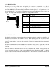
signals.
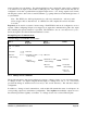
If connecting to an external device such as an electronic indicator, recorder or PLC / DCS input, the
loop can be powered by either the WI-I/O 9-x or the device. Externally powered loops to 27 VDC may
be connected by connecting the output between the "AO” terminal (positive) and the "COM" terminal
(negative). Zener protection of analog outputs provides protection against short periods of over-voltage
but longer periods may result in module damage.
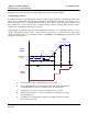
Note that the common is connected internally to ground and no other point in the analog loop should be
grounded. If the external device has single-ended grounded inputs, then a signal isolator must be used.
Analog outputs may also be configured to individually turn off (0 mA) if no command message is
received to that output for a certain period. . See Chapter 4 Configuration for further details.
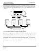
DEVICE
_
Note:
COM on WI-I/O 9-x
is connected to
ground/earth. If
the external power
supply cannot be
grounded, a loop
isolator must be
used.
+
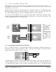
Connecting to a floating input device, powered from the WI-I/O 9-x
+24V
AO 1
COM
WI-I/O 9
+V
-V
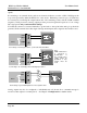
DEVICE
+
+24V
AO 1
COM
WI-I/O 9
_
Connecting to an externally powered floating-input device
+V
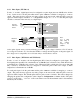
DEVICE
AI
+24V
AO 1
COM
WI-I/O 9
Signal
Isolator
Connecting to a grounded input device via a signal isolator