
Manual

WI-I/O 9-x_WI-I/O-EX-1-S-x 2.16 Page 23
2.4.6 Pulse Input (WI-I/O 9-1)
For the ”-1” module, digital input 1 may be configured as a pulse input (max rate 100 Hz, min. off time
5 ms). In this mode, both the pulse rate and the pulse count are available for mapping to a remote
output. The pulse rate may appear at any analog output on the remote unit, while the pulse count can
appear at a Pulse Output on another ”-1” or Digital/Pulse Output on a ”-3” or “-4” unit. The pulse input
should be connected in the same way as a digital input.
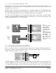
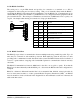
Active pulse signals can be connected directly provided the peak voltage is between 3.5–13V and the
low voltage is less than 1.5V. Note that the WI-I/O 9-x will ground the negative of the pulse signal. If
the voltages are not compatible, use a solid state relay to isolate the two devices.
2.4.7 Pulse Inputs (WI-I/O 9-2 and WI-I/O 9-4)
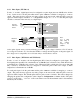
For the ”-2” and ”-4” modules, the four digital inputs (DI 1-4) may be configured as pulse inputs. The
first digital/pulse input DI 1 has a maximum rate of 1000 Hz (min. off time 0.5 ms), while DI 2-4 have
a maximum rate of 100 Hz (min. off time 5 ms). When using DI 1 at high pulse rates (more than 100
Hz), a divide by 10 function may be configured to reduce the pulse count at the output, as Pulse
Outputs have a maximum rate of 100 Hz.
For each pulse input, both the pulse rate and the pulse count are available for mapping to a remote
output. The pulse rate may appear at any analog output on the remote unit, while the pulse count can
appear at a Pulse Output. The default update time for pulse counts is 1 minute. This can be changed by
changing the update time configuration (refer Chapter 4 Configuration for further details). The pulse
count is a 16 bit value - “roll over” of the count when it exceeds the maximum value is automatically
handled by the modules.
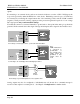
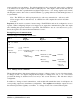
+
_
DI 1
COM
WI-I/O 9
Passive
transistor
device
+
_
+
_
DI 1
COM
WI-I/O 9
External
power
supply
+
_
Active pulse device
Note:
Use a solid
state relay if
the voltage
range is not
suitable.