
Manual

WI-I/O 9-x Wireless Module User Manual v2.16
WI-I/O-EX-1-S-x Serial Module
Page 24
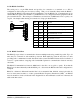
2.4.8 Pulse Output (WI-I/O 9-1)
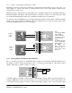
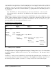
A single FET output to common rated at 30VDC, 500 mA is provide for the pulse output "PO". This
output accurately recreates the pulses counted at a pulse input at another module.
If the counter device requires a voltage pulse signal (such as electronic or elector-mechanical counters),
use the 24V analog loop supply, or the 12V BAT supply for the voltage source. Use a by-pass diode if
the counter is inductive.
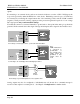
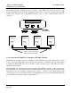
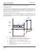
Some devices such as PLC counter modules power the pulse loop. For these devices, connect to the PO
and COM terminals of the WI-I/O 9-x. The COM terminal will connect a ground/earth to the external
device. If this is not suitable, use a solid state relay to isolate the external device.
Although the count is accurately re-created, the rate of output pulses may not accurately reflect the
input rate. The actual input pulse rate may be configured to appear at an analog output if required.
Note that the pulse rate and accumulated value will remain accurate even if a period of communications
failure has occurred. The maximum output rate is 100 Hz.
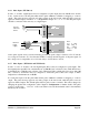
2.4.9 Pulse Output (WI-I/O 9-3 and WI-I/O 9-4)
The first four digital outputs on the ”-3” and ”-4” modules may also be used as pulse outputs. The
outputs are FET output to common rated at 30VDC, 500 mA. The outputs will provide a pulse signal
of up to 100 Hz. The outputs accurately recreate the pulses counted at pulse inputs at a ”-1”, ”-2” or “-
4” module.
Although the count is accurately re-created, the rate of output pulses may not accurately reflect the
input rate. The actual input pulse rate may be configured to appear at an analog output if required.
Note that the pulse rate and accumulated value will remain accurate even if a period of communications
failure has occurred.
_
+
+24V
PO
COM
WI-I/O 9
Use by-pass
diode if counter
is inductive.
COUNT
+
_
+
_
+24V
PO
COM
WI-I/O 9
Use solid-state
relay isolator if
voltages are not
compatible