
Manual

WI-I/O 9-x Wireless Module User Manual v2.16
WI-I/O-EX-1-S-x Serial Module
Page 26
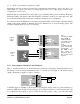
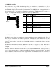
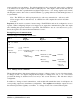
The modules include a terminating resistor on-board. If the WI-I/O 9-x module is the first or last
module in the RS485 chain, then the terminating resistor may be connected by operating the single DIP
switch in the end-plate next to the RS485 terminals. “On” or “down” means that the resistor is
connected.
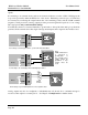
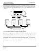
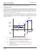
2.4.12 Connecting WI-I/O-EX-1-S-x Modules to WI-I/O 9-x Modules
WI-I/O-EX-1-S-x modules connect to a WI-I/O 9-x via the RS485 port on each module (refer to section
2.4.11). Up to 31 x WI-I/O-EX-1-S-x modules can be connected to a WI-I/O 9-x module. This number
is reduced for WI-I/O-EX-1-S-3 and –4 modules, as these modules use two unit addresses (refer to
chapter 4 of this manual).
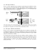
The WI-I/O-EX-1-S-x modules can be mounted next to the WI-I/O 9-x module, or they can be remote
from the WI-I/O 9-x. The reliable distance for a RS485 multi-drop line depends on the shielding of the
wire and how close it is installed to electrical noise sources - distances of more than ½ mile (1 km)
can be achieved by good installation methods. External RS485 isolators are recommended if the earth
potential difference between modules is greater than 7V.
A B
TERMINATING
RESISTOR SWITCH
WI-I/O 9-x
WI-I/O EX-1-S-x
RS485
A B
WI-I/O 9-x
WI-I/O EX-1-S-x
RS485
A B
WI-I/O 9-x
WI-I/O EX-1-S-x
RS485
A B
WI-I/O 9-x
WI-I/O EX-1-S-x
RS485
A B
Activate resistor-connection
switch at both end modul
es