
Manual

WI-I/O 9-x Wireless Module User Manual v2.16
WI-I/O-EX-1-S-x Serial Module
Page 46
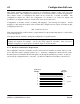
WI-I/O
9-1
WI-I/O
9-2
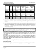
WI-I/O 9-3
First addr
(Even)
WI-I/O 9-3
Second addr
(Odd)
WI-I/O 9-4
First addr
(Even)
WI-I/O 9-4
Second addr
(Odd)
Output 1 DO 1 DO 1 D/P O 1 AO 1 D/P O 1 DIO 5
Output 2 DO 2 None D/P O 2 AO 2 D/P O 2 DIO 6
Output 3 DO 3 None D/P O 3 AO 3 D/P O 3 DIO 7
Output 4 DO 4 None D/P O 4 AO 4 D/P O 4 DIO 8
Output 5 AO 1 None DO 5 AO 5 DIO 1 DIO 9
Output 6 AO 2 None DO 6 AO 6 DIO 2 DIO 10
Output 7 PO None DO 7 AO 7 DIO 3 DIO 11
Output 8 None None DO 8 AO 8 DIO 4 DIO 12
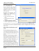
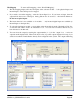
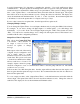
6. If you select a WI-GTWY-9-xxx as the destination module, you will be asked to select a I/O
Register as the destination “output”. Note that the grey-shaded I/O registers have already been
allocated.
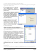
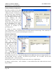
7. Select any intermediate repeater units needed to reach the destination address (entered in order of
nearest to furthermost repeater). You can either select from the list of configured units or enter the
unit address in the “Repeater” box. If no repeaters are required, do not enter anything in the
repeater boxes. If only one repeater address is required, enter the address in box 1 and leave the
other repeater boxes empty.
Note: Every module must have at least one mapping configured to another module. If no
mappings are required (for example, you are only using outputs at a module), then you need to
configure a mapping for a spare input to an unused output on another module.
It is possible to configure multiple mappings for an input - each mapping will generate separate
transmissions. We recommend that you do not configure multiple mappings to the same output as the
output will have the value of the last message that it receives. Each output should have only one
mapped input.
It is possible to map a digital input to an analog output - the output will be maximum value when the
input is on and minimum value when the input is off. It is also possible to map a analog input to an
digital output - the output will be on when the input is equal or greater than 12mA and off when the
input is less than 12mA.
For more information on using WI-I/O-EX-1-S-x modules, refer to Section 4.3.8.
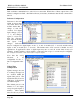
Edit existing mappings
To edit an existing mapping, double-click on the mapping line, or select the mapping line and “Edit”.